
External CV joint
Note: This procedure is much easier to perform if the drive shaft is removed from the vehicle. However, it is possible to disassemble the outer CV joint without having to separate the shaft from the transmission - you only need to hold the inner end of the shaft in the transmission while the steering knuckle is separated, and then the outer CV joint is removed. If this approach is to be used, follow paragraphs 1-3 and 5-9 of Chapter 2.
1. Remove the drive shaft (see chapter 2).
2. Clamp the drive shaft in a vice with soft jaws. If necessary, remove the dynamic vibration damper (where available), unscrew its two clamping screws.
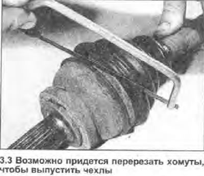
3. Cut the clamps of the protective cover and bend the cover away from the CV joint (see photo).
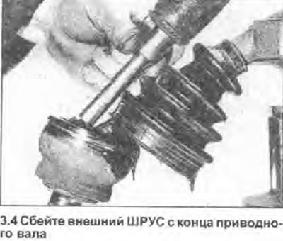
4. Using a pointed punch. put alignment marks on the CV joint housing and shaft, then with a hammer and punch (it should rely only on the internal assembly of the CV joint) knock the CV joint off the grooves of the shaft until the retaining ring is compressed in its groove and released (see photo).
5. Remove the CV joint from the shaft and pull off the protective cover. If the boot is not replaceable, wrap the threads and collars of the shaft with electrical tape first to protect the boot from sharp edges. Check the boot for cracks or other damage and replace if necessary. Replace both boot clamps.
6. Remove the retaining ring from the end of the shaft and discard it. Using a clean rag, remove as much grease from the CV joint as possible.
7. When installing, wrap the desired areas of the shaft with electrical tape to protect the boot from shaft grooves and other sharp edges. Install the small collar of the protective boot onto the shaft, then the boot itself, so that its edge falls into the corresponding groove, and then remove the tape.
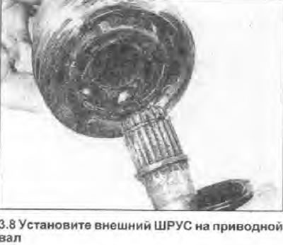
8. Place a new retaining ring in the groove closest to the end of the shaft, apply a small amount of grease and install the outer CV joint in place so that the end of the shaft, the retaining ring and the internal CV joint assembly are aligned, and also made before removing the marks. Protect the threads of the CV joint by temporarily installing the old driveshaft nut on it. Using a mallet, carefully drive the outer CV joint onto the shaft until the retaining ring is compressed in the groove (see photo).
9. Make sure that the retaining ring has worked by now trying to pull the CV joint off the shaft.
10. Fill the SHRUS with the type of lubricant specified in the Specifications; squeeze out the excess into the protective case.
11. Place the end of the protective boot into the groove of the CV joint housing and equalize the air pressure in the boot by carefully prying one of its sealing edges with a small screwdriver. Fasten the clamps of the protective cover.
12. If the dynamic vibration damper (where available) removed, install it as described in paragraph 27 or 28 below.
13. Install the drive shaft (see chapter 2).
Internal CV joint
Note: The description below assumes that the driveshaft will be removed and the inner CV joint disassembled. However, it is enough to remove only the outer CV joint (see note above), to remove and install the protective cover of the inner CV joint over the drive shaft. If this approach is taken, remove the dynamic vibration damper (where available), remove any rust build-up, etc. using emery cloth, and wrap around the sharp edges of the shaft (thread type) tape to protect the sealing edges of the boot from damage.
14. Remove the drive shaft (Chapter 2).
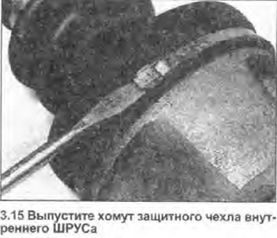
15. Loosen or cut the rubber boot clamps and bend the boot away from the CV joint (see photo).
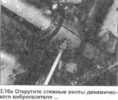
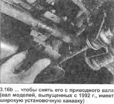
16. Clamp the drive shaft in a vise with soft jaws. If necessary, remove the dynamic vibration damper (where available), unscrew the two hex cap screws securing it to the shaft (see photo).
 |  |
17. Using a pointed punch, make alignment marks on the CV joint housing and shaft, then remove the CV joint housing, being careful not to lose the needle rollers of the three pivot bearings.
18. Place alignment marks on the inner CV joint assembly and shaft, then remove the circlip from the inner end of the shaft. Drive the inner pivot out of the grooves of the shaft, again taking care not to lose the bearing needle rollers.
19. Remove the protective cover from the shaft; if it cannot be replaced, wrap sections of the shaft with duct tape to protect the boot from the remaining retaining ring and other sharp edges. Check the protective boot for cracks or other damage and replace if necessary. Replace both clamps.
20. Using a clean rag, remove as much grease as possible from the CV joint.
21. When assembling, wrap certain areas of the shaft with duct tape to protect the boot from grooves, remaining retaining ring, and other sharp edges. Install the small collar of the protective boot and the boot itself onto the shaft, make sure that its end is in the corresponding groove of the shaft, then remove the tape.
22. Aligning the marks made before removing, slide the inner half-joint of the CV joint along the grooves of the shaft, then attach it by installing a new retaining ring in the groove closest to the end of the shaft. lose the needle rollers of the three CV joint bearings.
23. Install the CV joint housing in the working position, aligning the marks made before removing.
24. Fill the CV joint rolled in Specifications type of grease and place the excess in the protective pouch.
25. Place the end of the boot into the groove of the CV joint housing and slide the housing along the shaft several times to spread the grease around the pivot components and adjust the position of the boot. Equalize the air pressure in the boot by gently prying up one of its sealing lips with a small screwdriver, then secure the boot with the zip ties.
26. If the dynamic vibration damper (where available) removed, install it as follows.
27. On models manufactured before 1992 (without wide locating groove on the right drive shaft), completely clean and degrease the area of the shaft surface that is 80-170 mm away from the outer seating groove of the protective cover of the inner CV joint. Using a suitable adhesive to bond metal to rubber/plastic. Glue the two halves of the plastic insert of the vibration damper to the shaft at the location shown in Fig. 8.2. Install metal clips (along with their screws and washers), positioning them so that the joint of the clamps is at right angles to the joint of the plastic insert. Tighten the screws with a tightening torque specified specifications. When the glue is dry, make sure the vibration damper is securely attached to the cotton. After installing the drive shaft on the vehicle, make sure that the vibration damper is at least 5mm away from any other part of the vehicle, especially the bodywork and suspension (taking into account the extreme positions of the suspension components, possible when driving).
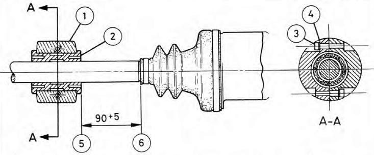
Pic. 8.2 Location (distances are given in mm) dynamic vibration damper on early models whose shaft does not have a mounting groove: section A-A is an illustration for all models
1. metal clip; 2. Plastic insert; 3. Coupling screw; 4. Spring washer; 5. The inner end of the vibration damper; 6. The outer edge of the groove for the protective cover of the inner CV joint.
28. On 1992 models, carefully clean the shaft and vibration damper components and install the two halves of the plastic insert into the wide groove of the shaft. Install metal clips (along with their screws and washers), positioning them so that the joint of the clamps is at right angles to the joint of the plastic insert. Tighten the screws with a tightening torque specified specifications. No need to use glue; provided that the vibration damper is properly seated in the groove, i.e. cannot slide on the shaft. In this case, the vibration damper can rotate on the shaft - this is quite acceptable.
29. Install the drive shaft (see chapter 2).