
Assembly diagram of the interior heater
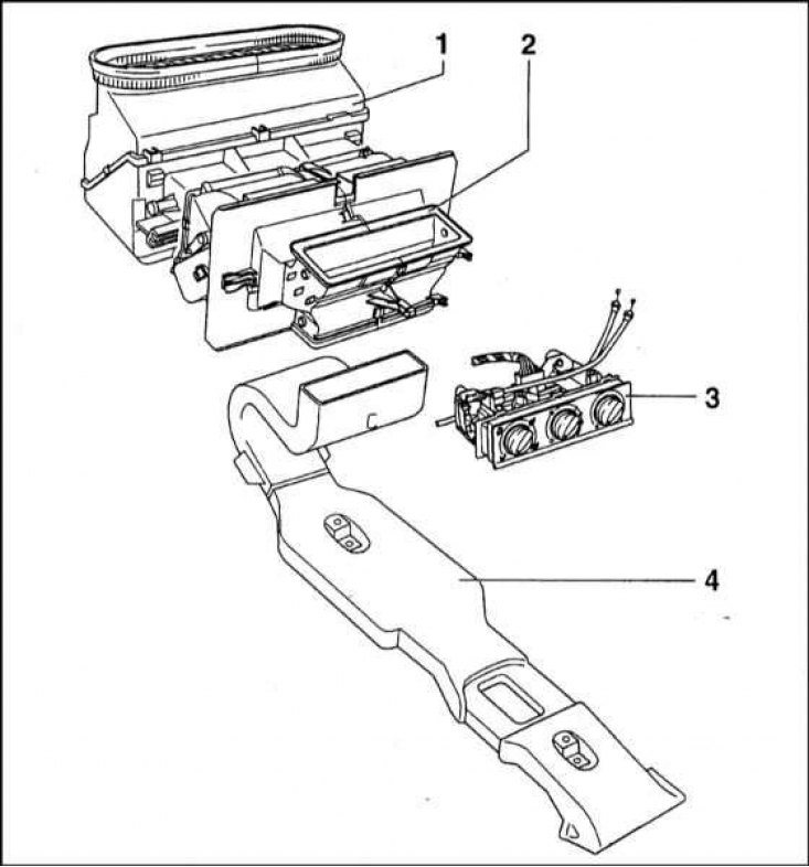
1 - Heater fan casing; 2 - Heater casing; 3 - Assembling the control of the parameters of the functioning of the heating / ventilation system; 4 - Air duct
Scheme of functioning of the heating / ventilation system
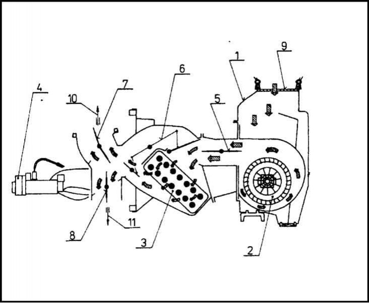
1 - Heater casing; 2 - Heater fan; 3 - Heat exchanger; 4 - Switch for selecting fan speed modes; 5 - Central damper; 6 - Baffle of the heat exchanger of the heater; 7 - Air distribution damper; 8 - Air distribution damper; 9 - Protective grille; 10 - For blowing the windshield; 11 - Into the footwells
The heating and ventilation system provides air exchange, as well as air heating in the car. In addition to the standard set of air supply to the front of the cabin, rear air ducts are also provided, the outlet diffusers of which are located in the rear doors. The system equipment includes: an air intake, a heater heat exchanger with a fan, air distribution ducts and outlet deflectors closed with decorative grilles.
The air duct, through which air enters the cabin from the outside, is located just behind the edge of the hood, directly under the base of the windshield.
The heater heat exchanger assembly, equipped with a fan, is housed in a plastic casing consisting of two halves, closed with covers at the front and at the back.
A drainage hole is provided in the bottom of the heat exchanger casing to drain rainwater that enters the assembly together with outside air, or during a car wash. An air duct is connected to the bottom of the casing.
The diagram of the functioning of the heating / ventilation system of the cabin is shown in the illustration.
On the considered models of cars heaters of production of the KSA company are used. The heat exchanger is made of aluminum, the side chambers are made of plastic. On the side of the heater, two pipes are removed, on which rubber hoses fixed with clamps are put on. The hose supplying the engine cooling liquid to the heat exchanger is connected to the inlet pipe, which is also heated by the liquid. The outlet hose is connected to the water pump nozzle
A valve is mounted in the underwater branch pipe, which makes it possible to mechanically regulate the flow rate of the liquid passing through the heat exchanger, accordingly changing the intensity of heating of the air supplied to the passenger compartment.
Placing the electric motor of the heater fan in the cold air stream ensures its uninterrupted operation for a long time due to the highly efficient removal of excess heat.
It should be remembered that the fan can only function when the ignition is on (key in position "I"). Turning on the fan and selecting its high-speed mode is performed by a rotary knob located on the control panel. The control panel for the operation of heating / ventilation systems is mounted in the lower part of the central section of the vehicle instrument panel.
The position of the adjusting valve, as well as the air distribution dampers located inside the heater casing, is also controlled using the rotary knobs located on the control panel.
In the heater casing, on a special connector, rheostats for controlling the speed modes of the heater fan are installed, which provide a step change in the speed of the impeller. The rheostats are cooled by blowing them with an air stream. A bimetallic fuse is installed next to the rheostats, which turns off the fan drive electric motor in case of overheating or a short circuit in the power circuit.
If necessary, the supply of outside air to the passenger compartment can be completely blocked by turning on the closed air circulation mode. This feature allows you to avoid the entry of foul-smelling or heavily dusty air into the cabin, however, the mode should be used only for a short time, due to the fact that the air closed in a small volume quickly stagnates.