



Models not equipped with air conditioning
Assembling the heater casing
1. If necessary, loosen the nuts securing the upper suspension strut supports and remove the strut brace from the vehicle.
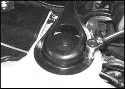
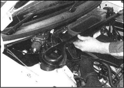
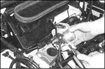
2. Acting in accordance with the instructions given in the relevant Part of the Chapter Power supply system, perform the following procedures:
- a) On 1.3L SPFI petrol models, remove the air cleaner assembly;
- b) On 1.3L MPFI petrol models, unbolt and remove the throttle body assembly from the intake manifold. Set the assembly aside without disconnecting the accelerator cable, wiring and connecting hoses;
- c) On 1.6L petrol models, remove the air intake sleeve;
- d) On diesel models, remove the upper section of the intake manifold.
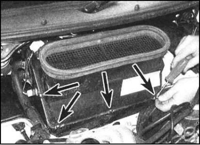
3. Release the air intake mount fasteners to the upper part of the heater casing...
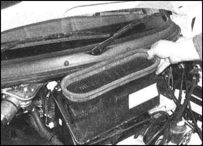
...remove the air intake from the engine compartment.
4. Remove the battery (see Chapter Engine electrical equipment).
5. Remove the instrument panel and cigarette lighter (see Chapter On-board electrical equipment).
6. Locate and disconnect the electrical connector from the interior heating/ventilation control panel on the left side of the cowling.
Note: If access to the connector is restricted, it can be disconnected by removing the cover.
7. Through the hole for installing the cigarette lighter, release the fastening clamp of the air supply hose to the foot well to the base of the heater casing.
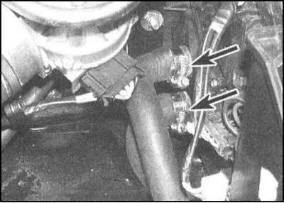
8. In the engine compartment, pinch the heating system hoses to minimize coolant loss. Place a rag under the heater heat exchanger fittings, then loosen the clamps and disconnect both hoses. Immediately wash away any spilled coolant with water. Cover the heater casing with rags.
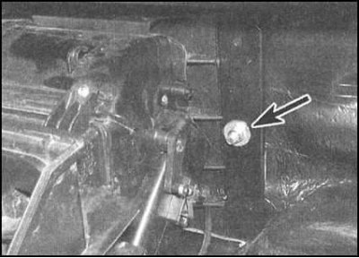
9. Loosen the nuts securing the heater housing assembly to the engine compartment bulkhead.
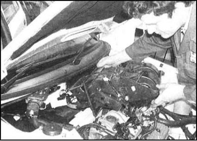
10. Have an assistant make sure the system control panel is released from the instrument panel, then lift the cover assembly with the control panel and remove it from the vehicle,
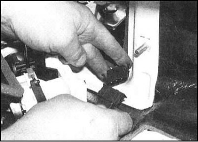
...as access is provided, disconnect the electrical wiring connector. Place the assembly with the fittings facing up to minimize coolant loss.
11. Installation is carried out in reverse order. Particular attention should be paid to the following points:
- a) Before installation, check the condition of the bulkhead gasket and replace it if necessary;
- b) Ensure that the casing assembly is seated correctly and that the air ducts and pipes are securely fastened, and only then proceed to tightening the fastening nuts;
- c) Ensure that the corresponding hoses are securely fastened to the heat exchanger fittings;
- d) Finally, add the required amount of mixture of the required composition to the cooling system.
Control panel for interior heating/ventilation system
1. Remove the heater housing assembly from the control panel.
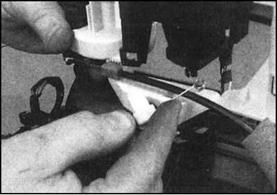
2. Try to remember the installation position of each of the drive cables (the cable ends are color coded). Then, using pliers, release the retaining clips and disconnect the cables from the panel.
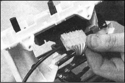
3. Disconnect the electrical wiring from the heater fan drive motor, then separate the panel from the housing.
4. Assembly is carried out in the reverse order. Ensure that all drive cables are correctly laid and securely fastened in their regular places. Before final installation of the casing assembly on the vehicle, check the proper functioning of the control switches.
Electric fan drive motor - petrol models
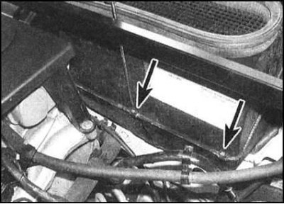
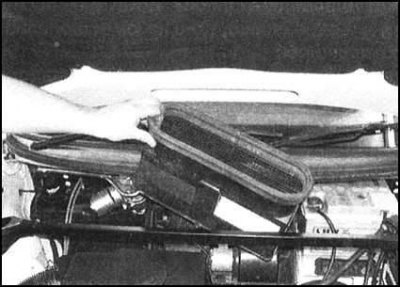
1. Loosen the fasteners and remove the air intake from the heater casing.
 |
 |
2. Remove the battery to gain access.
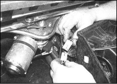
3. Follow the wiring from the electric motor of the heater fan to the connector. Disconnect the connector...
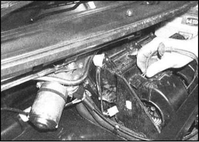
and release the rubber bushing of the harness from the casing, then pull the harness out of the casing.
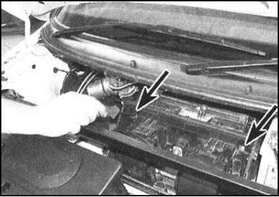
4. Remove the mounting screws, release the fasteners and remove the fan motor support plate assembly from the heater housing.
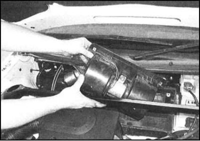
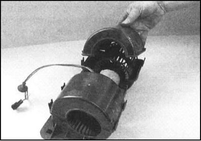
(Article reprinted from the website: «www.skodabook.ru»)
5. Remove the covers by releasing them from the clips,
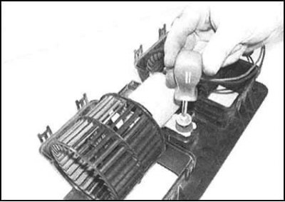
then loosen the screw
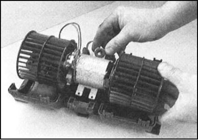
and separate the motor from the plate.
6. Assembly is carried out in the reverse order. Finally, do not forget to install the battery in place and check the freedom of rotation of the heater fan impeller.
Electric fan drive motor - diesel models
1. Remove the battery to gain access.
2. Release the clamps and remove the air intake from the heater casing.
3. Disconnect the fan wiring connector.
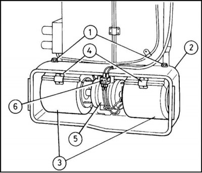
4. Loosen the mounting nuts and remove the electric motor support plate assembly from the heater housing.
5. To gain access to the motor, release the clamps and remove the covers. Unscrew the clamping bolt and remove the motor from the support plate.
6. Installation is carried out in the reverse order. Finally, install the battery in place and check the impeller for free rotation.
Heater Fan Motor Resistor - Petrol Models
1. The resistor is located in the engine compartment and is secured to the right wall of the heater housing assembly. On left-hand drive models, the battery must be removed to access the resistor.
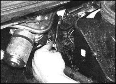
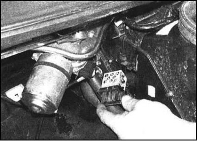
2. Disconnect the electrical connector, then release the resistor from the clips and remove it from the housing.
 |
 |
3. Installation is carried out in the reverse order. Make sure that the resistor is securely fastened.
Heater Fan Motor Resistor - Diesel Models
1. The resistor is located in the engine compartment and is secured to the left wall of the heater housing assembly. To access the resistor, the battery must be removed.
2. Disconnect the electrical connectors. Try to remember the order in which they were connected.
3. Remove the mounting screws and remove the resistor from the housing.
4. Installation is carried out in reverse order.
Heater heat exchanger - petrol models
1. Remove the heater casing.
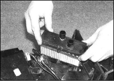
2. Loosen the mounting screw and remove the heat exchanger from the casing.
Caution! Try not to injure your fingers on the sharp edges of the heat exchanger plates!
3. Before installation, check the condition of the heat exchanger sealing foam. Carefully place the assembly in its regular place in the casing and tighten the fastening screw securely. Then install the casing in place.
Heater Heat Exchanger - Diesel Models
1. On left-hand drive models, remove the battery.
2. On all models, clamp the hoses going to the heater heat exchanger in the engine compartment. Place a rag under the fittings, then release the clamps and disconnect both hoses. Collect any traces of spilled liquid, cover the heater casing with rags.
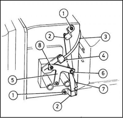
1 - Fastening nut; 2 - Drive cable; 3 - Drive cable; 4 - Cable guide; 5 - Executive lever; 6 - Clamp bolt; 7 - Cable; 8 - Clamp bolt
3. Loosen the clamp bolts and disconnect the drive cables from the heat exchanger thermostat rod. Loosen the clamp and disconnect the upper cable housing, then loosen the upper and lower mounting nuts and remove the damper actuator lever from the housing.
4. Carefully release the clips and remove the upper part of the heat exchanger cover from the heater casing.
5. Carefully remove the heat exchanger.
Caution! Do not cut your fingers on the sharp edges of the plates!
6. Installation is carried out in the reverse order. Do not forget to check the condition of the sealing compound.
Models equipped with air conditioning
Warning! Do not disconnect the refrigeration lines under any circumstances (see section Air Conditioning System - General Information and Precautions)!
Assembling the heater casing with the control panel
The removal and installation procedures of the assembly should be entrusted to specialists of the car service workshop due to the need to disconnect the refrigeration pipes from the expansion valve of the A/C evaporator.
Electric motor for heater fan drive
1. In the engine compartment, remove the fasteners and remove the heat shield from the heater casing.
2. Locate and disconnect the fan motor wiring connector at the front of the shroud. Push the rubber grommet into the shroud.
3. Disconnect the vacuum hose from the intake throttle body diaphragm assembly. Also disconnect the rod from the diaphragm linkage.
4. Unscrew the mounting screws, release the clamps and, releasing the electrical wiring, remove the air intake from the upper part of the heater casing.
5. Remove the mounting screws and drive motor assembly.
6. Installation is carried out in the reverse order. Ensure that the electrical wiring bushing is seated correctly. Finally, check the proper functioning of the air intake flap.
Fan Motor Resistor
1 The resistor is located in the engine compartment on the left wall of the heater housing. To access the resistor, remove the battery.
2 Disconnect the electrical connector, release the resistor from the clips and remove it from the casing.
3 Installation is carried out in the reverse order. Make sure that the resistor is securely fastened to the casing.
Heat exchanger heater
The removal and installation procedures of the heat exchanger should be entrusted to car service specialists due to the need to disconnect the refrigeration lines from the evaporator expansion valve (see section Air Conditioning System - General Information and Precautions).