
Cooling Fan Installation Diagram
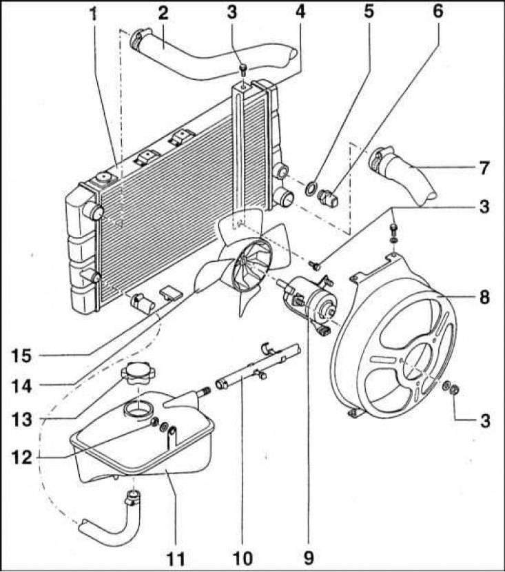
1 - Radiator; 2 - Upper radiator hose; 3 - Bolt; 4 - Mounting bracket; 5 - Sealing washer; 6 - Temperature-sensitive sensor-switch; 7 - Lower radiator hose; 8 - Casing (diffuser) fan; 9 - Drive electric motor; 10 - Hose for the release of air plugs; 11 - Expansion tank; 12 - Fixing nut; 13 - Expansion tank cover; 14 - Fan impeller; 15 - Rubber support pad
Attention! Be aware that when the engine is hot, the cooling fan may run even after the ignition is turned off. Be careful!
General information
Models 1.3 l
The cooling system fan is designed to create a forced air flow through the radiator heat exchanger in order to provide the necessary heat removal intensity.
The fan is located behind the radiator. For its drive, an electric motor of the PAL 443 132 166 010 type with a power of 55 W is used.
A 4-bladed plastic impeller is put on the motor shaft. The electric motor is placed in a diffuser, fixed on the upper and lower walls of the radiator heat exchanger by means of four M6x10 bolts. Three bolts are used to fasten the electric motor to the diffuser housing.
The fan is turned on at a coolant temperature of 97±2°C, and turned off at 88°C (models without A/C).
Models 1.6 l without K/V
The fan has an increased diameter (280 mm). For the drive, an electric motor manufactured by Bosch with a power of 130 W is used.
Note. Same fan but smaller (250 mm) used on 1.3 l models equipped with A/C.
The fan is turned on at a temperature of 95±2°C. shutdown - at 88°C.
Diesel models without K/V and petrol models 1.6 l with K/V
Attention! The electrical circuit of the electric motor is arranged in such a way that the fan can continue to function even after the ignition is turned off - be careful!
The fan diffuser is shifted to the left and is fastened with two bolts on the left and one on the right. Fan impeller - 6-bladed with a diameter of 300 mm.
The Gate fan is mounted on the diffuser with three bolts.
The first speed mode of the fan is switched on at a temperature of 95±2°С, and switched off - at 84°С. The second speed mode is activated at a temperature of 102±3°C. shutdown - at 91°С.
Examination
1. Power is supplied to the cooling fan through the ignition switch and fuse (see chapter Onboard electrical equipment). The circuit also includes a temperature-sensitive fan switch screwed into the radiator wall.
2. In the event of a fan failure, the condition of the fuses should always be checked first. If there are no signs of failure, start the engine and warm it up to normal operating temperature, then leave it running at idle. If the fan does not work for several minutes (or before the temperature meter detects overheating), turn off the ignition and disconnect the sensor-switch wiring harness. Connect the two pins of the electrical connector with a jumper and turn the ignition back on. If the fan now starts to function, replace the faulty sensor-switch.
3. If the fan still does not work, check that the sensor-switch connector is properly powered by the battery (12 V). If there is no power, check the condition of the relevant wiring (the fan motor may have failed, or the fuse has blown). If no problems can be identified, check for continuity between the ground terminal of the sensor-switch and ground. If there is no continuity, then the grounding is broken and it is necessary to make appropriate repairs.
4. If the performance of all the above checks does not reveal the cause of the fan failure, you should check the condition of the impeller drive electric motor. Disconnect the electrical connector and apply battery power directly to the motor terminals. If the motor does not work this time, replace it as an assembly.
Removing
1. Disconnect the negative cable from the battery.
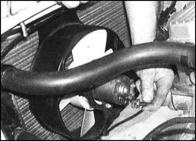
2. Disconnect the electrical wiring from the fan motor,
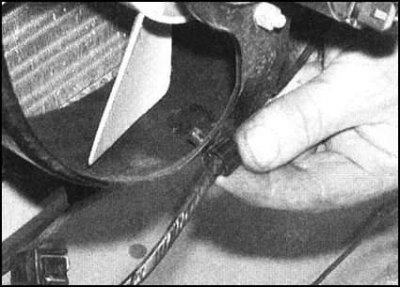
then release the wires from the intermediate clips on the casing,
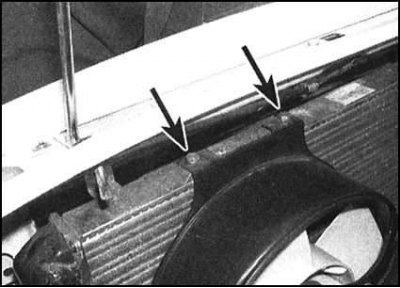
unscrew the fixing bolts
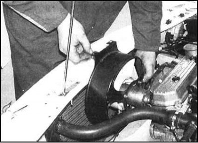
and remove the fan assembly shroud from the rear of the heatsink.
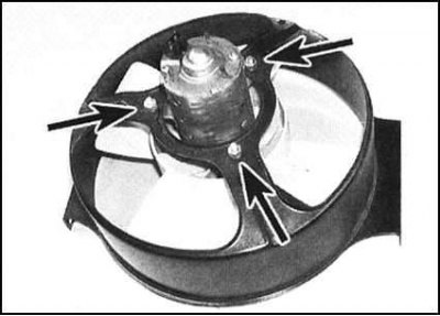
3. If necessary, give the fixing nuts, remove the washers and separate the motor from the assembly casing. The impeller can now be removed from the motor after releasing the retaining clip.
Installation
1. Install the motor assembly on the casing, put on the washers, then screw on the fixing nuts and tighten them firmly. If removed, put the impeller on the motor spindle and secure it with a retainer.
2. Place the assembly on the radiator and secure it with bolts.
3. Restore the original wiring connection (remember to connect the battery).
Disassembly
1. Drain the coolant.
2. Disconnect the coolant hoses from the radiator.
3. Disconnect the electrical wiring from the temperature-sensitive sensor-switch and the fan drive motor.
4. Remove the mounting bracket.
5. Turn out fixing screws. And remove the heatsink assembly with the fan.
6. Give fixture of a diffuser to a radiator.
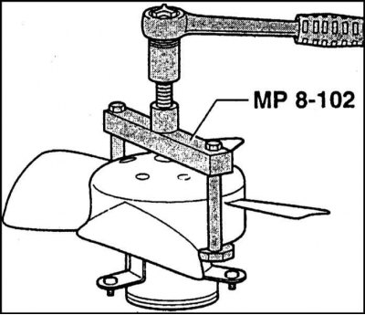
7. Remove the fixing screws and remove the impeller using the special tool (MP8-102).
Assembly
Assembly is carried out in the reverse order of dismantling. Pay special attention to the following points:
- a) The impeller should be pressed onto the assembly, but in no case should it be stuffed;
- b) Tighten all fasteners with the required force;
- c) Check the correct fit of the components;
- d) Be sure to add fresh coolant to the system.