



Air conditioning system component connection diagram
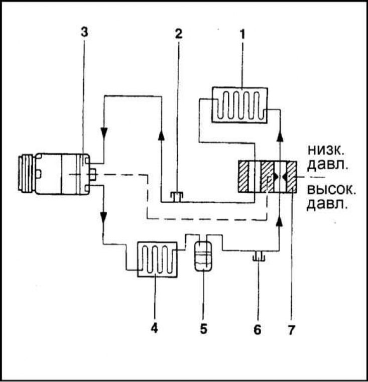
1 - Evaporator; 2 - Bottom valve for filling and emptying the system; 3 - Compressor; 4 - Capacitor; 5 - Thermal relay; 6 - Upper valve for filling and emptying the system; 7 - Valve block
Layout of the components of the air conditioning system on the vehicle
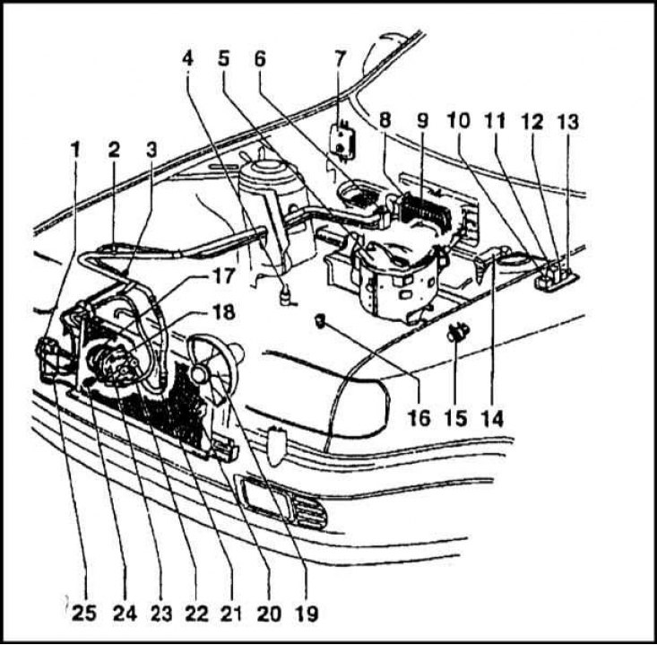
1 - Temperature sensor switch; 2 - Bottom valve; 3 - Upper valve; 4 - Speed controller; 5 - Evaporator body; 6 - Valve block; 7 - Electronic block; 8 - Evaporator; 9 - Thermal relay; 10 - Supercharger relay; 11 - Compressor relay; 12 - Second speed fan relay; 13 - Fuse; 14 - ECU injection system; 15 - Solenoid valve; 16 - Temperature sensor; 17 - Electromagnetic coupling; 18 - Pressure relief valve; 19 - Fan; 20 - Capacitor; 21 - Pipeline; 22 - Pipeline; 23 - Compressor; 24 - 2-stage temperature-sensitive sensor-switch of the cooling system fan; 25 - Valve
The air conditioning system (A/C) is an optional extra for LXi and GLXi models with 1.3 and 1.6 litre petrol engines. It is not possible to equip models with a diesel engine with the A/C system. The functional diagram of the air conditioner is shown in the illustrations. The components of the A/C system are manufactured in the Czech Republic, Germany and Japan.
The system allows to reduce the temperature and humidity of the air supplied to the passenger compartment, which significantly increases the comfort of the driver and passengers in the car.
Structurally, the K/V evaporator is combined with the heater housing, the rear part and air distribution flaps of which remain unchanged. In the front part of the casing, an evaporator with its own fan is installed.
In cooling mode, the air conditioner operates on the same principle as a household refrigerator. The gaseous refrigerant is sucked into the belt-driven compressor and enters the condenser installed in front of the radiator, where it gives off its heat, passing into the liquid phase. Next, the liquid refrigerant enters the evaporator through the expansion valve, where it turns from a high-pressure liquid into a rarefied gas. This phase transition is accompanied by a sharp drop in temperature and, accordingly, cooling of the evaporator. Then the refrigerant returns to the compressor and the cycle repeats.
The air blown through the evaporator is cooled and enters the heater assembly, where it is mixed with hot air coming from the heat exchanger of the latter, giving it a temperature selected by the operator. The resulting mixture of the required characteristics (temperature and humidity) is supplied to the vehicle interior.
If it is necessary to heat the air in the passenger compartment, the system operates as a conventional heater on standard models (see section Interior heating/ventilation system - general information).
The compressor is installed in the left front corner of the engine compartment, its drive is carried out by a multi-rib auxiliary belt, which simultaneously drives the generator. The belt tension is adjusted by changing the position of the generator.
The compressors are manufactured by Sanden, which assigns them the designation SD7H13. The maximum rotation speed of the compressor is 7000 rpm. The drive shaft is connected to the compressor shaft using an electromagnetic clutch, which smooths out jerks when the device is turned on and ensures stable operation of the generator and smooth changes in engine load.
The compressor capacity is 129.2 cm³. The compressor is mounted on the engine using four bolts.
The K/V condenser is installed in front of the engine cooling system radiator. The radiator fan power consumption is 250 W. The temperature-sensitive relay, receiving information from the temperature sensor in the thermostat, switches off the compressor when the coolant temperature reaches 114°C.
The air conditioning control panel is equipped with two switches: on/off switch for the system and air temperature control.
In case of malfunction of the system, please contact a specialized workshop or a Skoda branded service center.
Precautionary measures
Special precautions must be taken when servicing any components of the refrigeration system of the air conditioning system. The same applies to procedures that require disconnecting refrigeration lines.
Warning! Liquid refrigerant (freon) is used as a working fluid in the car air conditioning system. Freon, as a chemical substance, is potentially dangerous, and therefore, only a qualified specialist can be allowed to handle it. If the refrigerant comes into contact with exposed areas of skin, it can cause deep frostbite. Freon itself is not poisonous, but when in contact with an open flame, it forms a highly toxic gas, therefore, inhaling freon gas through a lit cigarette can lead to the most dire consequences. In addition, the release of freon into the atmosphere causes significant damage to the environment due to the irreversible destruction of the ozone layer.
If there is a suspicion that the refrigerant level in the air conditioning system has decreased, you should stop using it further, as this may result in compressor failure.
Any disconnection of components and refrigeration lines of the cooling system should be entrusted to specialists.