



Cooling system diagram (1.3L carburetor engine)
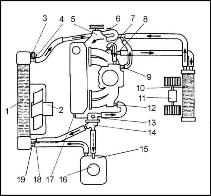
1 - Radiator; 2 - Fan; 3 - Temperature sensitive switch; 4 - Outlet pipe; 5 - Water pump; 6 - Cork; 7 - Outlet from the intake manifold to the carburetor; 8 - Outlet from the intake manifold to the heater; 9 - Carburetor outlet; 10 - Heater heat exchanger; 11 - Heater fan electric motor; 12 - Inlet manifold inlet branch; 13 - CTS; 14 - Thermostat; 15 - Expansion tank; 16 - Expansion tank cap; 17 - Drain plug; 18 - Inlet manifold; 19 - Inlet manifold
All models of cars of the brand in question use a closed-loop cooling system operating under pressure. The system includes a water pump, the drive of which on 1.6 l models is carried out from the timing belt, and on others - from the auxiliary one, a radiator made of aluminum of a cross-flow design, an electric fan, a thermostat, a heater heat exchanger, as well as all connecting fittings and electric switches. Cold coolant from the radiator enters the water pump through the lower hose, which supplies it to the galleries of the block and cylinder head (and also in the heat exchanger of the interior heater). After removing heat from the cylinder surfaces, combustion chambers and valve seats, the coolant reaches the bottom of the thermostat, which is initially closed. Next, the coolant passes through the heater heat exchanger, after which it returns back to the water pump.
The functional diagram of the engine cooling system is shown in the accompanying illustration. The cooling system functions as follows: a centrifugal water pump takes cold coolant from the bottom of the radiator through the lower radiator hose and pumps it under pressure through the galleries of the water jacket of the block and cylinder head, and if equipped, also through the oil cooler heat exchanger. Having taken heat from the cylinders, combustion chambers and valve seats, the liquid enters the lower part of the thermostat, the valve of which remains closed during the engine warm-up stage, and then opens. In addition to cooling the engine, the coolant is also used to heat the car's interior. For this purpose, a heater heat exchanger is included in the cooling system tract, passing through which the liquid returns back to the cylinder block.
Until the engine has warmed up to a certain temperature, the coolant continues to circulate in a short circuit, passing only through the block and cylinder head, as well as through the heater heat exchanger. As soon as the engine temperature reaches the set value, the thermostat opens, as a result of which the radiator is connected to the liquid circulation circuit. In the radiator, convective heat transfer from the liquid to the oncoming air flow occurs, the efficiency of which is determined by the developed area of the radiator heat exchanger fins and the speed of the air flowing around them. If necessary, additional cooling of the radiator is provided by turning on the electric fan of the cooling system. When the liquid reaches the lower cavity of the radiator, the cycle is repeated.
An electric fan, the operation of which is controlled by a temperature-sensitive sensor-switch of the cooling system, is installed behind the radiator. As soon as the coolant temperature reaches a certain set value, the fan is switched on, as a result of which the airflow over the radiator heat exchanger increases, which leads to an increase in the efficiency of heat transfer.
Precautionary measures
Caution! To avoid scalding, never remove the expansion tank cap or disconnect any cooling system components when the engine is hot. If it becomes necessary to remove the expansion tank cap before the coolant has completely cooled down, (such situations should be avoided if possible), the excess pressure in the system should be released first. Wrap the tank cap with a thick layer of rags, then slowly unscrew until hissing occurs. When the hissing indicating the release of steam stops, slowly unscrew the cap to the end. If the hissing does not resume at the last stage of unscrewing, the cap can be removed. During the entire procedure, do not bend your face over the neck of the tank, put on rubber gloves to protect your hands.
Try to avoid antifreeze getting on exposed skin and body panels. Accidental splashes should be washed off immediately with plenty of clean water. Never leave drained or fresh coolant stored in an open container. Wipe up spills with a rag immediately. Remember that the sweet smell of antifreeze can attract the attention of children and animals. Even a small amount of coolant getting into the digestive tract of a living organism can have the most serious consequences, including death.
Information taken from this resource: skodabook.ru
Remember that when the engine is hot, the cooling system fan continues to operate even after the ignition is turned off - take care of your hands, try not to allow hair or edges of clothing to come into contact with the impeller blades.
Precautions for models equipped with air conditioning are listed in Section Air Conditioning System - General Information and Precautions.