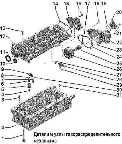
1. Valve: not subject to processing, only grinding is allowed; mark installation position for reinstallation
2. Cylinder head: due to small tolerances, modification of the valve seats is prohibited.
3. Mounting pin: camshaft housings
4. Oil scraper cap
5. Valve spring
6. Valve spring plate
7. Hydraulic compensator: mark the installation position for reinstallation; lubricate work surfaces before installation
8. Valve cotters
9. Roller rocker: mark the mounting position for reinstallation; check roller bearings for ease of rotation; lubricate work surfaces before installation
10. Locking cap: replace after disassembly; removal: with the camshaft housing installed, pierce with an awl on one side of the cover and pry off; Installation: Using a suitable drift, e.g. drift -3390-, push flush without sealant
11. Shaft seal
12. Camshaft housing: with integrated camshafts
13. Bolt
14. O-ring; replace after removal
15. Lid
16.8 Nm
17. Centering sleeve; only for vehicles with engine code CRKB
18. 8 Nm: only for vehicles with engine code CRKB
19. O-ring: only for vehicles with engine code CRKB; replace after removal
20. Valve 1 for camshaft adjuster -N205-: only for vehicles with engine code CRKB
21. 8 Nm: only for vehicles with engine code CRKB
22. Sleeve: variable valve timing; only for vehicles with engine code CRKB
23. Centering sleeve: only for vehicles with engine code CRKB
24. Gasket: only for vehicles with engine code CRKB
25. Control valve, 50 Nm: only for vehicles with engine code CRKB
26. Camshaft adjuster: only for vehicles with engine code CRKB
27. O-ring: replace after disassembly
28. Hall sender -G40-
29.9 Nm
30. Locking bracket: for hydraulic compensator
31. Mounting pin: camshaft housings
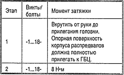
Camshaft housing - torque and tightening order
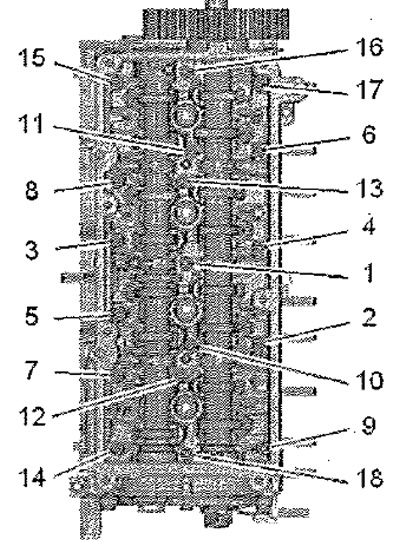
Tighten the bolts step by step in the sequence shown.