
Carefully! When performing installation work, especially in the engine compartment due to its dense layout, the following regulations must be observed: lines of all types (fuel, hydraulic, coolant, coolant, brake fluid, vacuum) and wires should be routed in the original factory order (using appropriate fasteners). To prevent damage to hoses, pipes or wires, sufficient clearance must be maintained to all moving or hot parts. During installation, install all heat-shielding cuffs in their places.
Remove the top engine cover. Remove the front upper coolant pipe. Remove the lower coolant pipe. Remove left coolant pipes. Remove intake pipe. Remove toothed belt from camshaft. For vehicles with engine code CLHA, CLHB, CKFB, CKFC, CRVC, CUPA
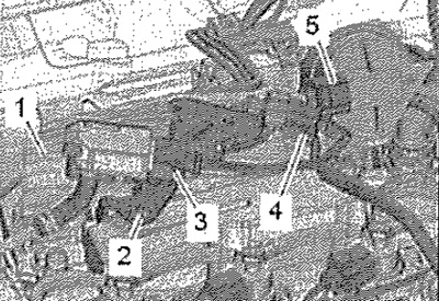
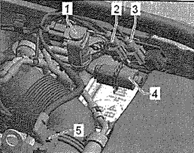
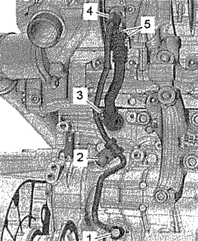
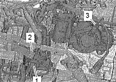
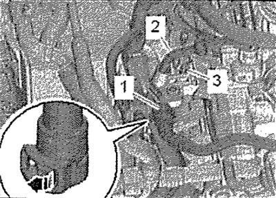
Open the heat shield -1-. Remove the electrical connector -4- from the bracket and disconnect it, freeing the electrical cable. Disconnect electrical connectors -3, 5- and hang out wiring harness. Remove screw -2- and move bracket with differential pressure sender -G505- back.
For vehicles with engine code CRKB
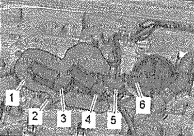
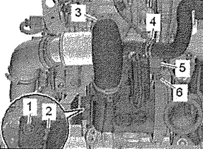
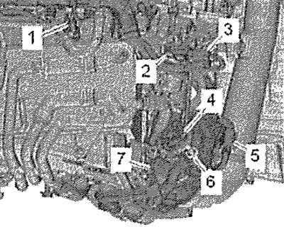
Open the heat shield -1-. Unplug electrical connectors -3, 5, 6- and move wiring harness clear. Unscrew screw -2-, Disconnect connector -4-.
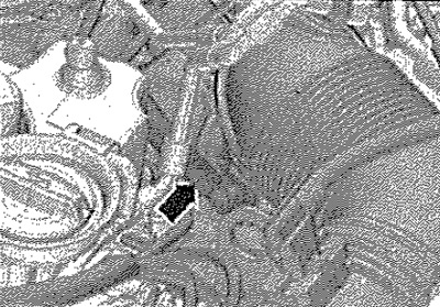
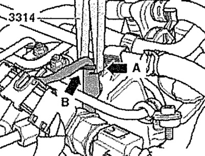
Disconnect vacuum hose -arrow- and lay to one side. Remove holder with differential pressure sensor and place back.
All
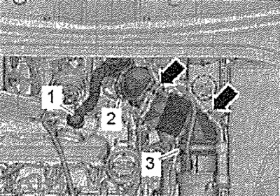
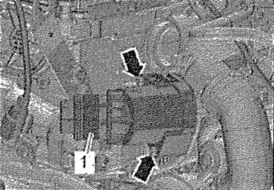
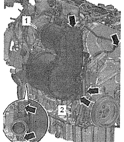
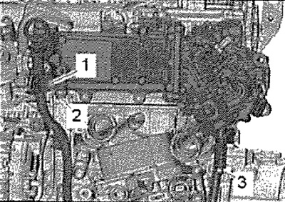
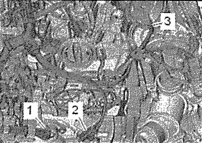
Detach hose -1- for crankcase breather from cylinder head cover by pressing hose clips. Unclip vacuum hoses -arrows- at breather pipe. Unscrew screw -2-, move air duct with intake manifold connector to rear and detach from turbocharger, -position 3- is ignored.
Remove screws -arrows- and remove prechamber -1-.
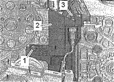
Loosen clamp -1- and remove coolant hose. Loosen screw -2-, unscrew screw -3- and swivel coolant hose to one side.
Disconnect connectors and release wiring harnesses.
2. Exhaust gas temperature sender 4 -G648-
3. Exhaust gas temperature sender 3 -G495-
Remove electrical connector -4- for lambda probe -G39- from bracket, unplug and move electrical cable clear.
Vehicles with all-wheel drive
Remove the exhaust gas recirculation cooler.
Vehicles with front wheel drive
Press heat shield aside and unplug connector -5-. Loosen hose clamp -3- and remove air hose. Loosen clamp -4- and remove coolant hose. Remove screw -1- and loosen screw -2-. -Position 6- ignore.
All
Remove screw -1- and remove clamping sleeve. Loosen pin -2- and press coolant pipe back a little. Unscrew bolts -arrows-, press back exhaust gas aftertreatment module and, on front-wheel drive vehicles, also the exhaust gas recuperation cooler.
Unscrew screw -2- and union nut -4-, unscrew screws -3, 5-, remove oil return pipe. -Position 1-ignore.
Vehicles with auxiliary heater
Raise retaining clips -1- and loosen clamp -3-, disconnect coolant hoses. Unscrew nuts -arrows- and detach coolant pipes.
All
Remove screw -2-, screws -1, 3, 4- only loosen.
For vehicles with engine code CRKB
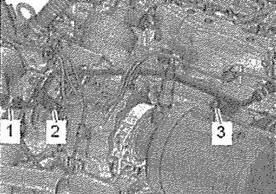
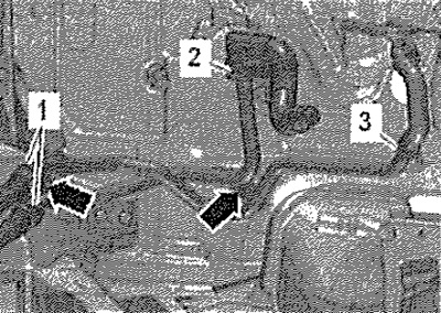
Disconnect connectors -1, 3-. Loosen clamp -2-.
All
Disconnect and release connectors.
1. Charge air temperature sender after intercooler -G811 -
3. Charge pressure sender -G31-
4. Intake air temperature sender -G42-
5. Throttle valve control unit -J338-
Remove screws -2, 7- and remove coolant hose -6-. Remove bolt -1- for oil dipstick guide tube. Remove screws -2, 3- for intake manifold bracket.
For vehicles with engine code CRKB
Remove throttle valve control unit -J338-.
All
Remove the camshaft housing. Unplug connector -3- and remove from cover -2-. Remove screw -1- and remove cover.
Unlock catch -arrow-, disconnect vacuum hose -1-. Detach vacuum hose -2-. Remove screw -3-.
Unplug electrical connector -2- for coolant temperature sender -G62-. Loosen clamp -1- and remove coolant hose. Detach vacuum hose -3-.
Disconnect electrical connectors from glow plugs. Set the wiring harness aside.
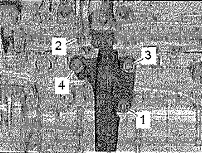
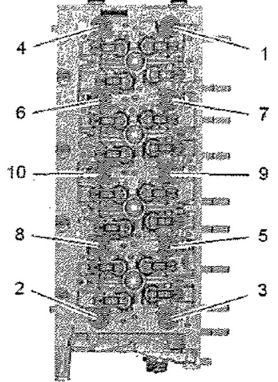
Loosen cylinder head screws in sequence -1...10-.
Note: The assistance of a 2nd mechanic is required to remove the cylinder head from the engine compartment.
Tilt the cylinder head to the left, remove it from the rear of the timing belt cover and at the same time remove the tensioner pulley. Take care not to damage the turbocharger oil return line. Lay the cylinder head in such a way that the oil return line is not kinked. If necessary, place a block of wood under the exhaust manifold.
Attention! Careless handling of the removed cylinder head can damage the glow plugs. Do not put the removed cylinder head with glow plugs on the flattened plane, because the glow plugs protrude somewhat beyond it.