
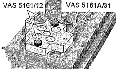
Cylinders 1, 3, 4
Fit guide plate -VAS 5161A/31- to cylinder head. The inscription -A- points towards the turbocharger. The inscription -E-points towards the intake manifold. Secure guide plate with knurled screws -VAS 5161/12-otruki. Position the thumb screws as shown in the illustration.
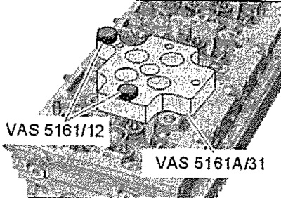
Cylinder 2
Fit guide plate -VAS 5161 A/31- to cylinder head. The inscription -A- points towards the turbocharger. The inscription -E-points towards the intake manifold. Secure guide plate with knurled screws -VAS 5161/12- by hand. Position the thumb screws as shown in the illustration.
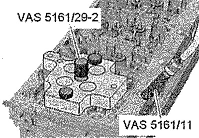
Continuation for all cylinders
Screw sealing pin -VAS 5161/29-2- into guide plate. Screw adapter -VAS 5161 /11- hand-tight into thread for corresponding glow plug.
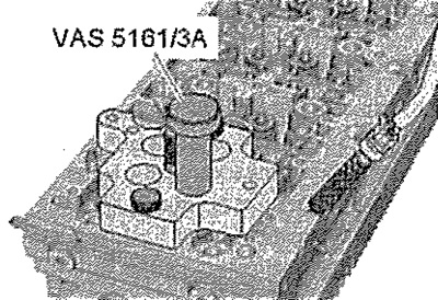
Insert punch -VAS 5161/3A- into guide plate and tap on it with a plastic hammer to loosen the valve cotters.
Screw bracket -VAS 5161/6- with plug -VAS 5161/5- into guide plate. Insert assembly cartridge -VAS 5161/8- with bushing -VAS 5161 A/31-1- into guide plate. Connect the adapter through a conventional adapter to a compressed air source and apply constant pressure. Minimum pressure: 0.6 MPa (6 bar) overpressure. Hook pressure lever -VAS 5161/2- onto adjustable stop and press assembly cartridge down.
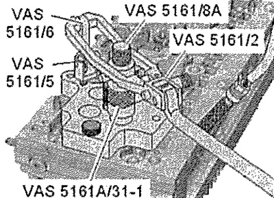
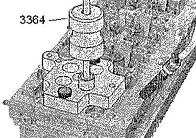
At the same time, turn the stem installed in the mounting cartridge clockwise until the fork located at its end enters the gaps between the crackers. Alternately turn the stem in one direction or the other - the crackers will be squeezed out of each other and fixed in the cartridge. Release the push lever. Remove the mounting cartridge with the sleeve. Remove valve spring with poppet. Remove oil seal using puller -3364-.
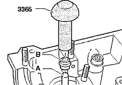
Attention! Risk of damage when installing valve stem seals. Put on the valve stem the plastic sleeve -A- supplied with the new valve stem seal -B-.
Lightly coat the sealing lip of the oil seal with oil. Put the oil scraper cap on the plastic bushing. Carefully press valve stem seal onto valve guide using drift -3365-. Remove plastic bushing.
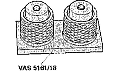
If the valve cotters have been removed from the assembly cartridge, they must first be inserted into the tool -VAS 5161/18-. The larger diameter valve cotters should point upwards. Insert valve spring with poppet. Press the mounting cartridge from above onto the mounting tool and grasp the valve cotters.
Reinsert assembly cartridge into guide plate -VAS 5161 A/31-. Press the lever and, turning the stem of the mounting cartridge first in one direction, then in the other, insert the crackers into place, Release the pressure lever with the stem still extended. Repeat the operation for each valve.
Installation
Installation in reverse order. Check that all valve roller levers are properly seated on the rod ends and hydraulic lifters. Install the camshaft housing. Installing glow plugs.