



Contents: For vehicles with engine code CLHA,…⬇ For vehicles with engine letter…⬇ All ⬇ Installation ⬇
Note: When carrying out work, install all heat-protective cuffs in their places.
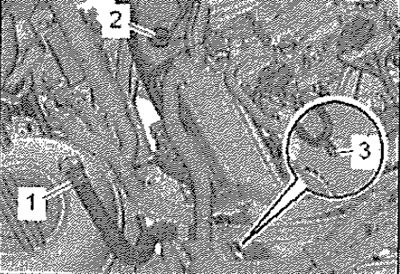
Remove the upper engine casing. Unscrew the exhaust gas temperature sensor 3 "C495" "pos. 2" using the tool from the 17 mm tool kit "T10395" and a suitable socket head. Unscrew the screw "3", release and press aside the pipeline. -Position 1- ignore.
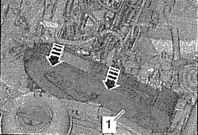
Unlock the "arrow" locks, unhook and press the upper part of the toothed belt casing "1" to the right. Remove the injectors.
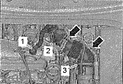
Disconnect hose "1" of the crankcase ventilation system from the cylinder head cover by pressing the hose clamps. Release the vacuum hoses "arrows" on the air pipe. Loosen clamp "3", disconnect the air duct from the mass air flow meter "G70". Unscrew screw-2-, move the air duct with the intake manifold fitting back and disconnect from the turbocharger.
For vehicles with engine code CLHA, CLHB, CKFB, CKFC, CRVC, CUPA
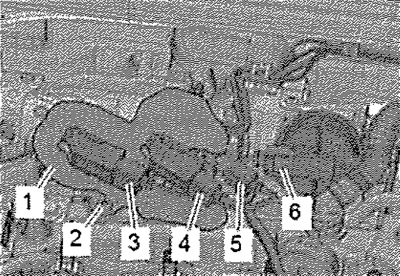
Open the heat shield "1". Disconnect electrical connectors -3, 4, 5- and hang up the wiring harness. Unscrew screw "2" and put the bracket with the differential pressure sensor "C505" back.
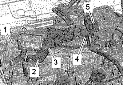
For vehicles with engine letter designation CRKB
Open the heat shield "1". Disconnect electrical connectors -3,5,6- and release the wiring harness. Unscrew screw "2". Disconnect connector "4".
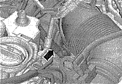
Disconnect and set aside the vacuum hose "arrow". Remove the holder with the differential pressure sensor and set it back.
All
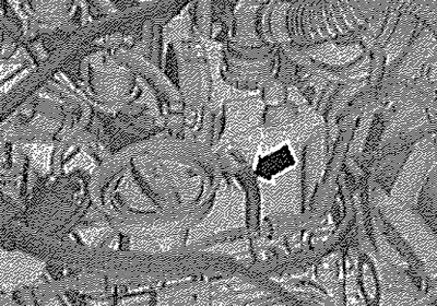
Disconnect the vacuum hose "arrow".
Loosen and unscrew the cylinder head cover bolts in the sequence Remove the cylinder head cover.
Installation
Installation in reverse order.
Note: Replace the sealing ring. Replace the cylinder head cover gasket and cylinder head mounting bolts if damaged or leaking.
Connect the vacuum hose.