
Instruction. The steering column control unit -J527- is fitted with an airbag coil spring and a return ring with slip ring -F138-. If the control unit is to be replaced, the function "Replace control unit" must be selected" the corresponding control unit.
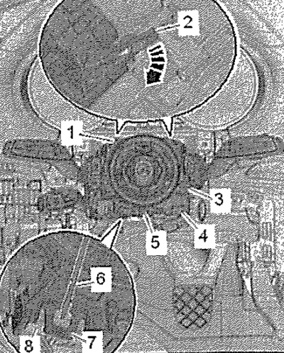
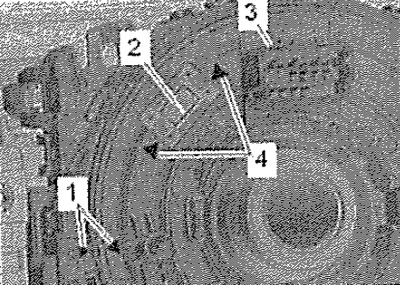
Remove steering wheel. Before removing the steering wheel from the steering column, the wheels must be in the straight ahead position. Remove the upper and lower steering column covers. Remove connector stopper -4-, press lock down and disconnect connector -3-. Remove retainer -1 - downwards, press downwards and unplug connector -2-. Unlock and disconnect connectors -1, 3, 4, 8- as shown in the figure. Carefully release connectors -8- from retainers -7- using a screwdriver -6-. Remove screw -5-. Unlock clutches -2- -arrow- and remove steering column control unit -J527- from steering column switch module.
Installation
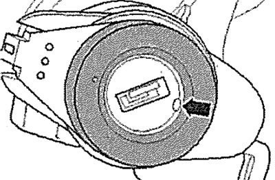
Installation in reverse order. Before sliding the control unit onto the switch module, the turn signal lever must be in position 0 and the annular rotor -3- must be in the correct installation position. Arrows -1- should be located opposite each other. Coil spring -2- must be visible in window between arrows -4-.
Adjust to correct position if necessary. Make sure that all retaining tabs and connectors are correctly engaged.
Adjusting the correct mounting position of the coil spring return ring
Performed only when there is doubt about the correct adjustment of the mounting position of the return ring rotor. Set the front wheels to the straight ahead position. Slowly turn the annular rotor -3- to the left as far as it will go. Turn the annular rotor by hand approx. 3.5 turns to the right so that: the arrows -1- are opposite each other; coiled spring -2- must be visible in the window between the arrows -4-. Install steering wheel, if necessary, secure ring rotor with transport protection or adhesive tape.
Pin assignment on steering column control unit -J527-
The current exact pin locations can be found in Wiring Diagrams, Electrical System Troubleshooting and Locations.
Removal and installation of the lock cylinder
Attention! Do not move the steering column lock without the lock cylinder, otherwise it will completely lock. A locked steering column shaft lock must be replaced. Do not remove the steering wheel. To remove the screws securing the lower trim of the steering column, turn the steering wheel 90°to the left and then to the right.
Remove the upper and lower steering column covers. Insert the ignition key into the lock cylinder and turn to the "Ignition ON" position. The cutout in the trim -arrow- is aligned with the hole in the ignition switch.
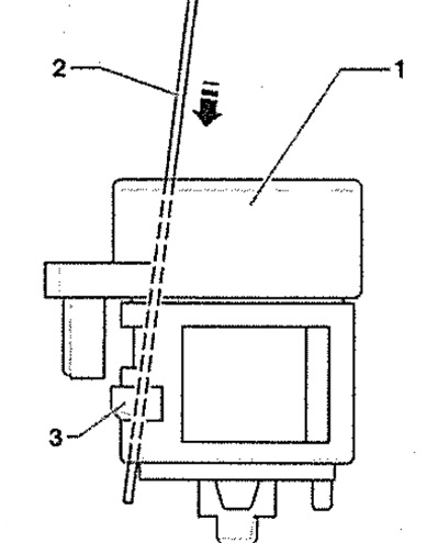
Insert steel wire -2- (diameter approx. 1.2 mm) hole next to the ignition key -arrow-. This releases the lock -3- and the lock cylinder -1- can be removed from the ignition switch. When pulling out the lock cylinder, carefully release the wire of the immobilizer reading coil. Disconnect immobilizer connector -1-.
Note: The immobilizer reader coil is attached to the lock cylinder and cannot be replaced separately.
Installation
Installation in reverse order. Insert the ignition key into the lock cylinder and turn the "Ignition ON" position". Insert the release wire -2- into the hole in the front part of the lock -arrow-. Slide the lock cylinder with readout coil into the steering column lock housing. Remove the wire and press the lock cylinder until it clicks audibly. Connect the connector to the reading coil.
Note: Pay attention to the correct position of the wire to the immobilizer pickup coil.