
Note: Do not rework the mating surfaces on the cylinder head cover from below and on the cylinder head from above. The camshaft bearings are integrated in the cylinder head and therefore in the cylinder head cover. Before removing the cylinder head cover, the tension of the camshaft drive chain must be removed. Install the cable ties in the appropriate places.
Remove soundproof cover. Remove the air filter housing. Remove the upper timing chain cover. Remove upper coolant pipe, Remove ignition coils. Disconnect electrical connectors.
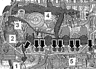
1. Air recirculation valve for turbocharger -N249-
2. Hall sender 3 -G300-
3. Fuel pressure regulator -N276-
Disconnect connectors -arrows- from camshaft adjuster actuators. Remove screw -5- and remove battery earth wire. Unclip the wiring harness -4- and move it to the front. Unlock catches -arrow-, pull wiring harness upwards out of bracket and press forward.
Attention. Risk of damage to the cooling system pipes. Do not change the shape of the bend in the cooling system pipes.
Remove screws -1, 2 and 3- and carefully swivel coolant lines back slightly.
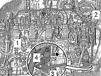
Unplug connector -1- from canister solenoid valve 1 -N80-. Press clamps on crankcase breather hose -2- and disconnect hose. Remove screws -arrows- and remove crankcase breather.
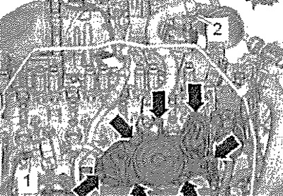
Remove camshaft adjuster actuators -arrows-.
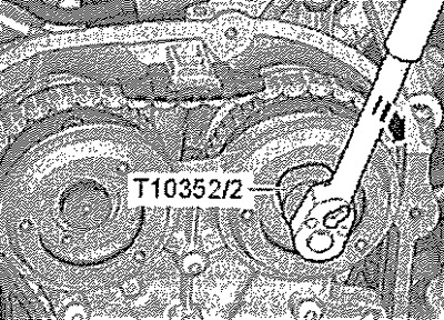
Attention. Regulator valves are left hand threaded.
Using special tool -T10352/2-, remove regulator valves (left-hand) in -direction of arrow-,
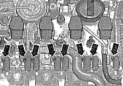
Remove screws -arrows- and remove bearing cap.
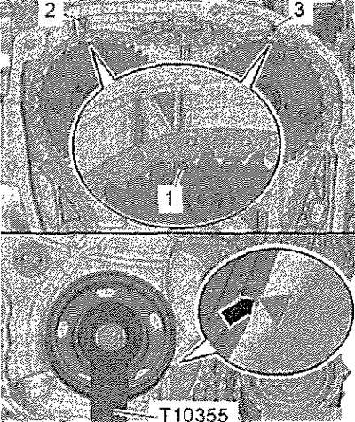
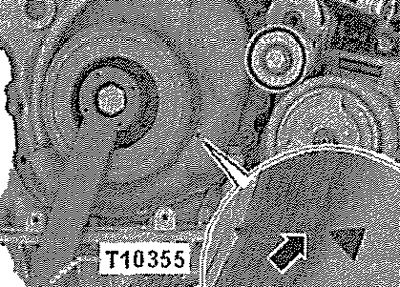
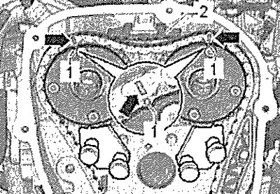
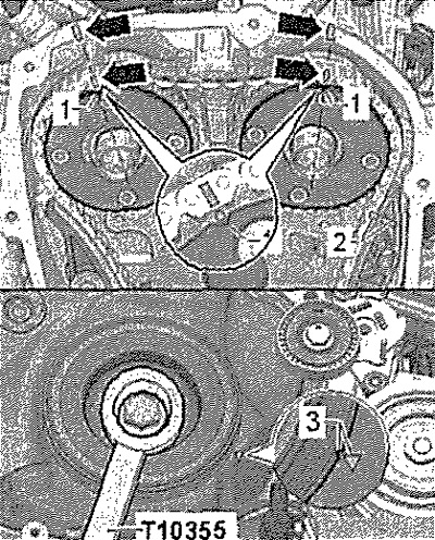
Use counterhold -T10355- to turn crankshaft poly V-belt pulley to "TDC" position". The notch on the crankshaft V-ribbed belt pulley and the mark on the lower timing chain cover must be opposite each other -arrow-. The marks -1- of the camshaft sprockets must be opposite the marks -2 and 3- on the cylinder head,
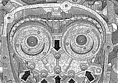
Opposite them, using a waterproof felt-tip pen, make marks on the camshaft drive chain and on the cylinder head -Pfeile- for marking on the sprockets -1-.
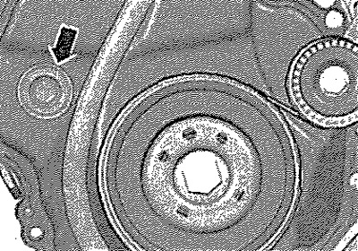
Remove plug -1-.
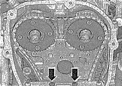
Remove screws -arrows-.
Screw in mounting lever -T40243- -arrows-. Compress the circlip -1- of the chain tensioner and hold firmly. Slowly press assembly lever -T40243- in -direction of arrow- and hold.
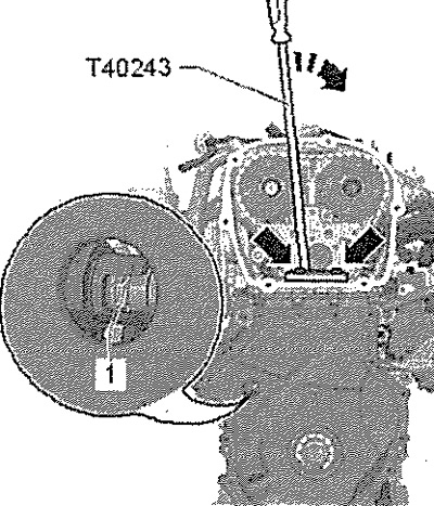
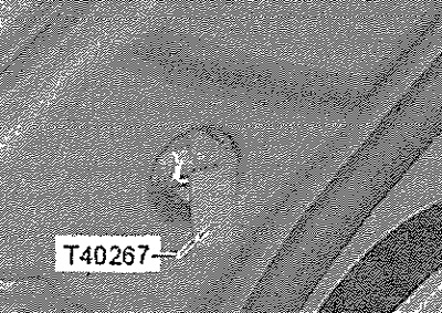
Lock chain tensioner with lock -T40267-. Remove mounting lever -T40243-.
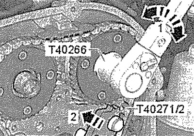
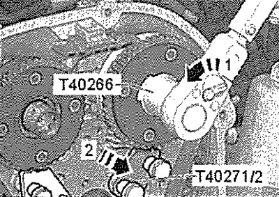
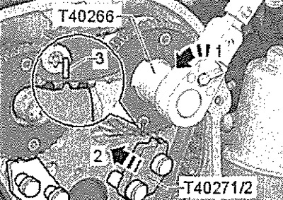
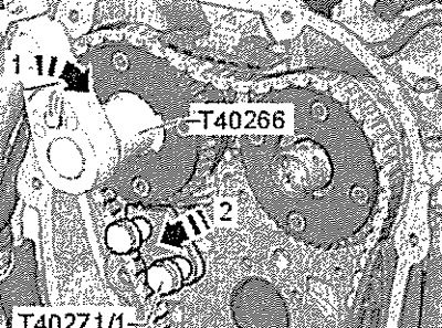
Screw camshaft clamp -T40271/2- into cylinder head and push into sprocket ring gear in -direction of arrow 2-, if necessary turn inlet camshaft using tool -T40266- in -direction of arrow 1-.
Remove screw -1- and slide tensioner shoe -2- downwards.
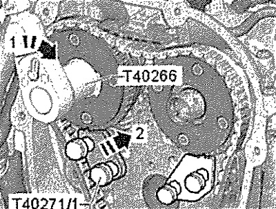
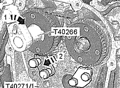
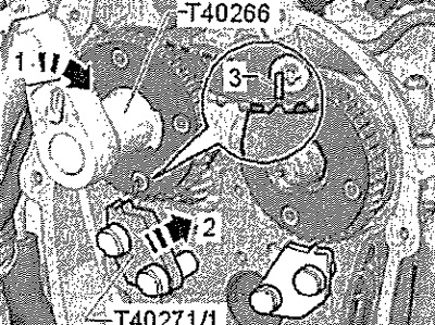
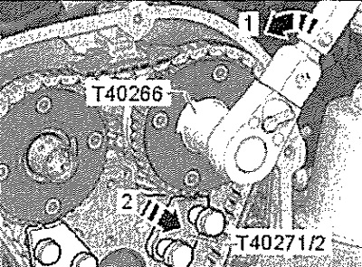
Screw camshaft clamp -T40271/1 - into cylinder head. Using special tool -T40266-, turn exhaust camshaft in -direction of arrow 1- and push camshaft retainer -T40271/1- into sprocket ring gear in -direction of arrow 2-.
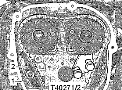
Mark chain sprockets opposite lugs of camshaft lock -T40271/1- and camshaft lock -T40271/2- -arrow- with a waterproof felt-tip pen. Remove the upper damper -1-, unlocking the retainer with a screwdriver and pushing the damper forward. Remove the camshaft drive chain from the sprockets.
Attention! Risk of damage to valves and piston crowns. If the camshaft drive chain is removed from the cylinder head, the crankshaft can no longer be rotated.
Using tool -T4Q266-, turn inlet camshaft in -direction of arrow 1-, push camshaft retainer -T40271/2- out of sprocket ring gear in -direction of arrow 2- and release camshaft.
Using tool -T40266-, turn exhaust camshaft in -direction of arrow 1-, push camshaft retainer -T4027V1- out of sprocket ring gear in -direction of arrow 2- and release camshaft. Remove HPV. Remove vacuum pump.
Unscrew the screws of the cylinder head cover in the sequence -1...6-. Remove the head cover. Take out the distributors.
Note: Do not remove or move the clutch which is part of the camshaft. Danger of contamination of the lubrication system and bearings. Open parts of the engine must be covered.
Installation
Note: Make sure that all roller tappet levers rest correctly on the ends of the valve stems. Neither piston should be at top dead center. Danger of contamination of the lubrication system and bearings. Open parts of the engine must be covered.
Remove sealant residue from cylinder head and camshaft housing with a chemical sealant remover. Clean the seating surfaces of oil and grease. Lubricate the running surfaces of the camshaft with oil. If the camshafts have been replaced, the markings -arrow- must be transferred to the new camshafts.
Attention! Risk of damage to valves and piston crowns. If the camshaft drive chain is removed from the cylinder head, the crankshaft can no longer be rotated.
Install intake camshaft -A- in cylinder head. Turn cams of cylinder 4 -arrows- upwards.
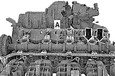
Install the exhaust camshaft into the cylinder head cover as shown. Pair of cams -A and B- must be aligned.
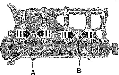
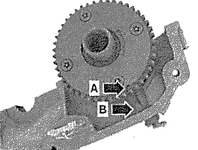
Turn exhaust camshaft until marks -A and B- line up.
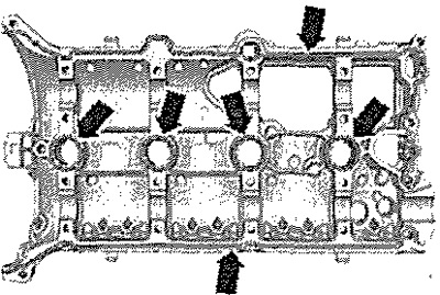
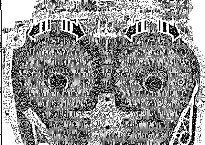
Cut off the tip of the sealant tube at the front mark (hole diameter about 2mm). Apply silicone sealant to the clean bonded surface of the cylinder head cover as shown in the illustration -arrow-. Sealant strip thickness: 2...3 mm.
Note: The cylinder head cover must be installed within 5 minutes after applying the silicone sealant. The sealant strip should not be wider than prescribed, because otherwise, excess sealant will enter the oil sump and clog the strainer in the oil intake pipe. Sealant must not be expired (see expiry date).
Note: Do not remove or move the clutch, it is part of the camshaft.
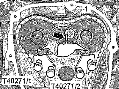
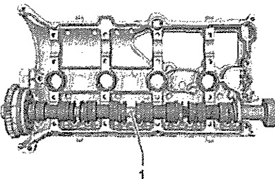
Lay cylinder head cover together with exhaust camshaft -1- on cylinder head.
Press lightly on the cylinder head cover with your hand and at the same time turn the camshaft slightly so that the cover sits on the cylinder head without tension. Replace cylinder head cover screws. Tighten the screws in several steps, tightening sequence.
Note: Make sure that the cylinder head cover is not twisted.
Turn inlet camshaft in -direction of arrow 1 until mark -3- is aligned with camshaft lock -T40271/2-. Push camshaft clamp -T4G271/2- into sprocket ring gear in -direction of arrow 2-.
Turn inlet camshaft in -direction of arrow 1- until mark -3- aligns with camshaft retainer -T40271/1. Push camshaft retainer -T40271/1- into sprocket ring gear in -direction of arrow 2-.
Use counterhold -T10355- to turn crankshaft poly V-belt pulley to position "TDC1. The notch on the crankshaft V-ribbed belt pulley and the mark on the lower timing chain cover must be opposite each other -arrow-.
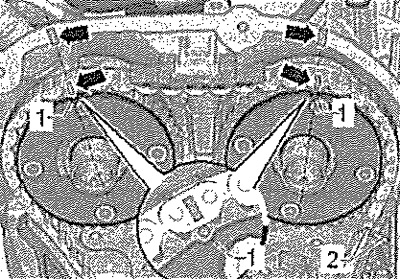
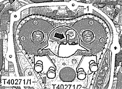
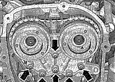
Fit the camshaft timing chain onto the sprockets, placing the marks on the target links -arrows- in the correct positions opposite the marks on the sprockets -1-. Install upper damper -2-.
Using tool -T40266-, turn exhaust camshaft in -direction of arrow 1-, push camshaft retainer -T40271/1- out of sprocket ring gear in -direction of arrow 2- and release camshaft.
Insert tensioner shoe -2- upwards and screw in screw -1-.
Using tool -T40266-, turn inlet camshaft in -direction of arrow 1-, push camshaft retainer -T40271/2- out of sprocket ring gear in -direction of arrow 2- and release camshaft.
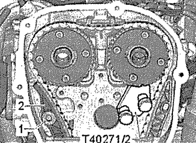
Check the valve timing, the marks on the camshaft timing chain and on the cylinder head -arrows- must match the marks on the sprockets. The markings on the camshaft timing chain and on the camshaft timing chain guide shoe -2- must be opposite each other. The notch on the crankshaft V-ribbed belt pulley must be located opposite the mark -3- on the lower timing chain cover.
Push on bearing cover and tighten screws -arrows- hand-tight. Remove retainer -T40267-. Tighten screws -arrows- for bearing caps. Install the regulator valves -pos. 6-.
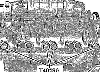
Push pins -T40196- into positions shown in illustration. Rotate crankshaft 4 turns in direction of engine rotation. Remove pins -T40196-. Install the upper timing chain cover.
Carry out chain length adaptation as follows. Switch on the ignition and select Tester. Press the following buttons in turn on the display: 01 - Engine electronics, 01 - Guided functions, 01 - Basic setting, 01 - Adaptation after work on the chain drive. Installation in reverse order.