
Note: Install cable ties in the appropriate places. Seal open intake manifold and exhaust ducts with suitable plugs, eg from engine plug set -VAS 6122-.
Drain coolant. Remove distributors.
Attention! Risk of damage to valves and piston crowns. With the camshafts removed, the crankshaft must not be rotated.
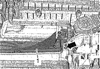
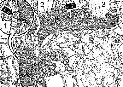
Remove downpipe from exhaust system with catalytic converter. Remove lambda probe -G39-. Unscrew left and right screws -arrow-. Detach bottom part of air duct -1- from mountings and remove.
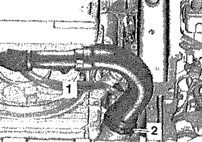
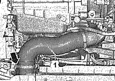
Loosen clamp -2- and remove air hose from intercooler. Seal open lines and connections immediately with clean plugs, eg from engine plug set -VAS 6122-. Pos. -1- can be ignored.
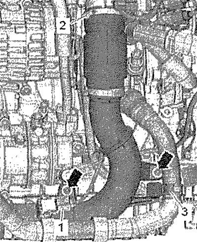
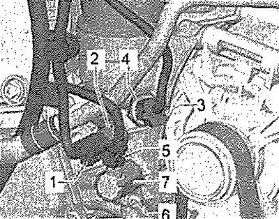
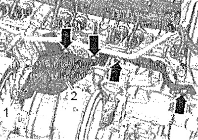
Loosen clamp -2-. Release coolant hose -3-. Remove screws -arrows-. Unplug connector -1- from charge pressure sender -G31- and detach right air pipe.
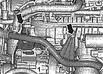
Loosen clamps -arrows- and detach coolant hoses. Unscrew coolant hose -1- to one side.
Disconnect the following electrical connectors.
1. Oil pressure sender -F22-
2. Low oil pressure sender -F378-
5. Piston cooling oil jet control valve -N522-
Remove screws -arrows-.
Unscrew screw -1, unscrew nut -3- and remove intake manifold bracket -2-.
Disconnect the following electrical connectors.
1. Throttle valve unit -J338-
2. Intake air temperature sender -G42- with intake manifold pressure sender -G71-
3. Fuel pressure sender -G247-
Remove connector -4- from bracket. Release wiring harness and press aside. Release wiring harnesses -1 and 2- from air duct. Loosen clamp -3-. Remove screws -arrows- and remove air pipe towards bottom.
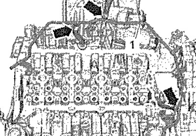
Loosen clamp -arrow- and remove air hose -1- from intercooler.
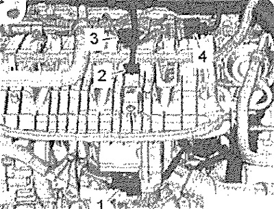
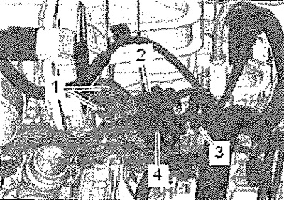
Unclip and unplug connector -3- for knock sensor 1-G61-. Disconnect connectors -2 and 4-. Pos. -1- can be ignored.
Disconnect connectors and release wiring harnesses.
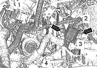
1. Intake manifold flap valve -N316-
2. Coolant shut-off valve -N82-
3. Coolant temperature sender -G62-
4. 3rd stage oil pressure sender -F447-
Unscrew bolt -arrow-, unscrew nut -1-. Remove heat shield -2-.
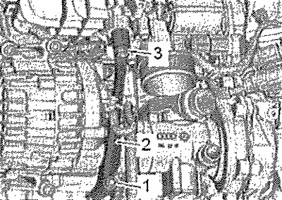
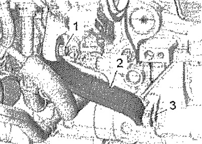
Remove screw -1-, screw -3- only loosen. Detach bracket -2- for turbocharger.
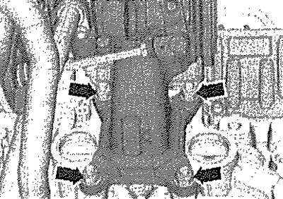
Remove nuts -arrows-. Remove turbocharger from cylinder head and bend down.
Remove screws -arrows-. Remove cylinder head bolts using socket wrench -T10070- in sequence -1...10-.
Note: Check that all pipes and cables are disconnected. When removing the cylinder head, pay attention to the shoes of the tensioners and dampers.
Remove cylinder head. Lay the cylinder head on a soft lining (foam or similar material).
Installation
Attention! Risk of damage to bonded surfaces. Carefully remove sealant residue from cylinder head and cylinder block. At the same time, do not leave furrows and scratches. Do not damage the cylinder block. There must be no oil or coolant in the blind holes for the cylinder head bolts. Risk of leaking cylinder head gasket. Remove the new cylinder head gasket from the packaging immediately before installation. The gasket should be handled carefully, trying not to damage the silicone layer and the rolling of the edges of the gasket. Risk of damage to open valves. Plastic gaskets to protect open valves can only be removed immediately before installing the cylinder head. Risk of damage to valves and piston crowns after working on the valve train. Crank the engine at least 2 revolutions to make sure the valve does not seize on start up. Replace screws that are tightened to a certain angle. Replace gaskets, lip seals and self-locking nuts. Pay attention to the differences in the use of sealants for bonded surfaces and cylinder head screws. When installing a cylinder head from an exchange fund, it is necessary to lubricate the friction surfaces of the hydraulic lifters, roller levers and camshaft cams with engine oil before installing the camshafts. Hose fittings and piping and charge air hoses must be free of oil and grease before installation. Secure all hose connections with appropriate standard clamps. In order to securely fasten the charge air hoses to their fittings, it is necessary to apply a rust converter to the augers of the previously used screw clamps before installation. When replacing the cylinder head or its gasket, replace the coolant and engine oil.
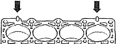
Apply cylinder head gasket. Check that dowel pins -arrows- are present in cylinder block. Observe the installation position of the cylinder head gasket, designation (detail number) should read from the side of the intake valves.
Attention! Make sure that no parts are damaged by the timing chain when rotating the crankshaft.
If the crankshaft has been rotated during this time: set the piston of the 1st cylinder to position "TDC" and turn the crankshaft back a little. Install cylinder head. Insert new cylinder head bolts and tighten by hand.
Note: It is not necessary to tighten the cylinder head bolts after the repair.
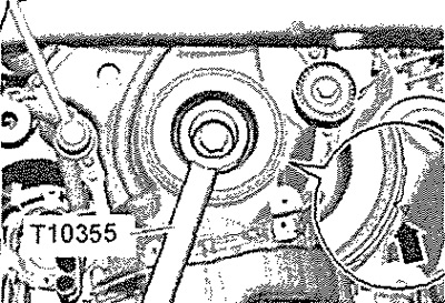
Use counterhold -T10355- to turn crankshaft poly V-belt pulley to "TDC" position". The notch on the crankshaft V-ribbed belt pulley and the mark on the lower timing chain cover must be opposite each other -arrow-.
Installation in reverse order. Install camshafts. Change engine oil. Replace coolant.