



Contents: Measuring battery voltage ⬇ Checking the battery terminals and…⬇ Checking the accessory drive belt ⬇ Checking the discharge indicator…⬇ Checking the voltage drop at the…⬇ Checking the output current ⬇ Voltage regulation test ⬇
Attention.
- Check that the battery wires are connected to the terminals.
- Never disconnect the battery cables while the engine is running.
Attention: Depending on the year of manufacture, different data readings are possible.
Measuring battery voltage
1. If 20 minutes have not passed since the engine stopped, turn on the ignition and turn on the electrical appliances (headlights, fan motor, rear fog lights, etc.) for 60 seconds to remove surface charge.
2. Turn off the ignition and switch off electrical appliances.
3. Measure the battery voltage between the negative and positive terminals of the battery.
Standard voltage: 12.5-12.9V at 20°C.
If the voltage is less than standard, charge the battery.
Checking the battery terminals and fuses
1. Check that the terminals are properly connected or not oxidized.
2. Check the electrical continuity of the fuses.
Checking the accessory drive belt
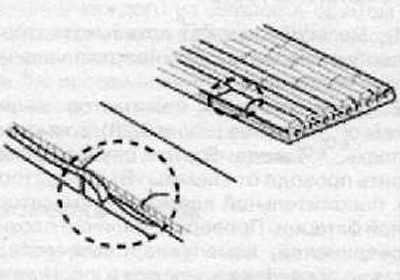
Visually inspect the belt for excessive wear, damage, etc.
If any defects are found, replace the accessory drive belt.
Note: Cracks on the rib side of the belt are acceptable. If the belt has missing pieces on the rib side, it must be replaced.
Checking the discharge indicator lamp circuit
1. Warm up the engine and then turn it off.
2. Turn off all additional devices.
3. Turn on the ignition. Check that the discharge indicator lamp lights.
4. Start the engine. Check that the low battery indicator lamp is not lit.
Checking the voltage drop at the generator output connector
1. Turn off the ignition.
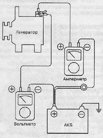
2. Disconnect the output wire from the "B" terminal of the generator. Connect the positive wire of the ammeter to the "B" terminal of the generator and the negative wire of the ammeter to the output connector. Connect the positive wire of the voltmeter to the "B" terminal of the generator and the negative wire of the voltmeter to the positive terminal of the storage battery.
Test
1. Start the engine.
2. Turn on the headlights and the fan motor and set the engine speed until the ammeter shows 20A. Then look at the voltmeter readings at this time.
Test results
1. The voltmeter can show the standard value. Standard value: 0.2V max.
2. If the voltmeter reading is higher than the standard (above 0.2 V), possibly bad wires. In this case, check the wires from the "B" terminal of the generator to the positive terminal of the battery. Check for bad connections, color change due to overheating of the wires, etc. Correct the deficiencies and test again.
3. After completing the test, set the engine to idle speed. Turn off the headlights, fan motor and ignition switch.
Checking the output current
Preparation
1. Before testing, check the following items and adjust if necessary.
Check the battery installed on the vehicle.
The output current of the battery used should be equal to that of a slightly discharged battery. With a fully charged battery, the test cannot be performed correctly due to insufficient load.
Check the tension of the generator drive belt.
2. Turn off the ignition.
3. Disconnect the negative terminal from the battery.
4. Disconnect the generator output wire from the "B" terminal of the generator.
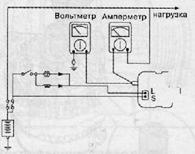
5. Connect a DC ammeter (0-150A) in series between the "B" terminal and the disconnected output wire. Connect the negative lead of the ammeter to the disconnected output wire.
Note: Tighten each connection securely as a large current will flow.
6. Connect a voltmeter (0-20 V) between terminal "B" and ground. Connect the positive wire to terminal "B" of the generator and the negative wire to ground.
7. Attach the engine tachometer and connect the negative battery cable.
8. Leave the hood of the vehicle open.
Test
1. Check that the voltmeter shows the same value as the battery voltage. If the voltmeter shows 0V, then there is a break in the circuit in the wires between the generator terminal "B" and the negative terminal of the battery or a bad ground connection.
2. Start the engine and turn on the headlights.
3. Turn on the high beam headlights and the heater fan switch to the HIGH position, increase the engine speed to 2500 rpm and look at the maximum output current value shown by the ammeter.
Note: After the engine starts, the charging current will drop quickly. Because of this, the above operation must be performed quickly to read the maximum current value correctly.
Result
1. The ammeter reading should be higher than the limit value. If lower, but the generator output wire is OK, then the generator must be removed from the vehicle and checked. Limit value: 70% of the rated current.
Note.
- The nominal output current value is shown on the nameplate attached to the generator body.
- The output current value varies with the electrical load and the generator temperature.
- Therefore, the rated output current cannot be obtained. If this happens, turn on the headlights or use the lights of another vehicle to increase the electrical load.
- The rated output current cannot be obtained if the generator or ambient temperature is too high.
- In this case, lower the temperature before performing the test.
2. After completing the output voltage check, reduce the engine speed to idle and turn off the ignition.
3. Disconnect the negative terminal from the battery.
4. Remove the ammeter, voltmeter and engine tachometer.
5. Connect the generator output wire to the "B" terminal of the generator.
6. Connect the negative battery cable.
Voltage regulation test
The purpose of this test is to check the voltage regulator.
(Data taken from this portal: skodabook.ru)
Preparation
1. Before testing, check the following items and adjust if necessary.
Check the battery installed on the vehicle.
Check the tension of the generator drive belt.
2. Turn off the ignition.
3. Disconnect the negative terminal from the battery.
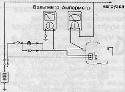
4. Connect a digital voltmeter between the generator terminal "B" and the vehicle chassis ground. Connect the positive lead of the voltmeter to the generator terminal "B". Connect the negative lead to the vehicle chassis or to the negative terminal of the battery.
5. Disconnect the generator output wire from the "B" terminal of the generator.
6. Connect the DC ammeter (from 0 to 150 A) in series between terminal "B" and disconnect the output wire. Connect the negative wire of the ammeter to the disconnected output wire.
7. Attach the engine tachometer and connect the negative battery cable.
Test
1. Turn on the ignition and check the battery voltage.
If the voltmeter shows 0 volts, it means there is an open circuit between the alternator "B" terminal and the battery and the negative battery terminal.
2. Start the engine. All instruments and lighting must be turned off.
3. Accelerate the engine to 2500 rpm and observe the voltmeter reading when the generator output voltage drops to 10 A or less.
Result
Note: The following data is a summary of the test results and may vary from model to model.
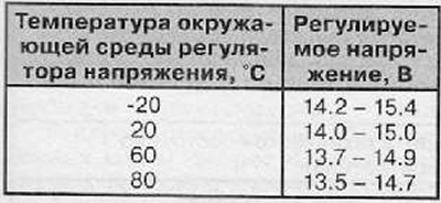
1. If the voltmeter readings match the values listed in the Adjustable Voltage column in the table below, the voltage regulator is working properly. If the readings differ from the standard values, the voltage regulator or alternator is faulty.
Table of adjustable voltages
2. After completing the test, reduce engine speed and turn off the ignition.
3. Disconnect the negative cable from the battery.
4. Remove the voltmeter, ammeter and engine tachometer.
5. Connect the generator output wire to the "B" terminal of the generator.
6. Connect the negative cable to the battery.