
Note. Disconnect the negative cable from the battery before proceeding with the procedures (see the remark given in Section General information and precautions).
Ignition switch/steering column lock
see chapter Suspension and steering.
Combined paddle shifters
The combined steering column switch consists of two separate units mounted on the vehicle's steering column.
A wiring harness is removed from the switch assembly, ending with an 8-pin connector.
The turn signal switch is equipped with a mechanical reset device that automatically turns off the alarm when the steering wheel returns to the straight position. A wiring harness is removed from the switch, ending with a 9-pin connector.
Removal and installation
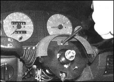
1. Remove the steering wheel (see chapter Suspension and steering).
2. On models without a driver's airbag, unscrew the fixing screw and lower the lower casing of the column, releasing it from the clamps. Remove the casing from the column.
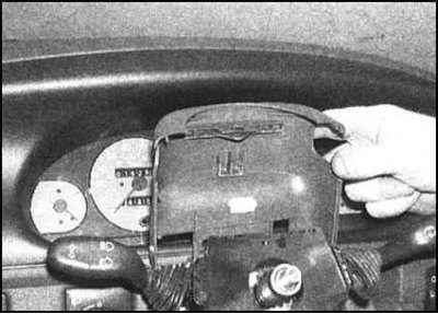
3. On all models, remove the fixing screw, release the clips, and remove the upper casing assembly from the instrument panel/switch holder.
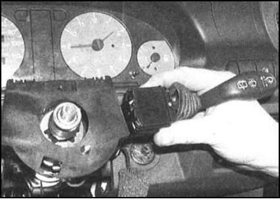
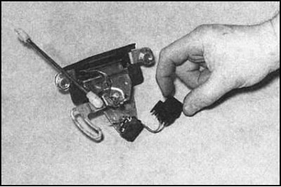
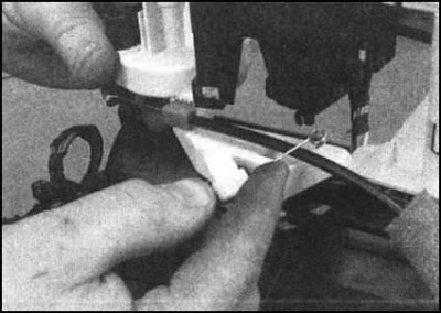
4. Now each of the switches can be removed from the holder individually after releasing the corresponding fasteners.
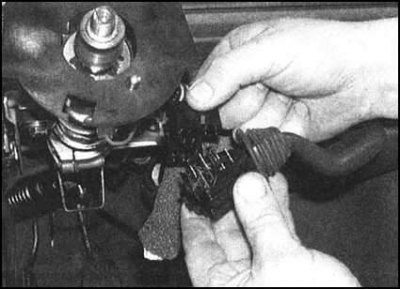
5. Having released the switch of their holder, disconnect from it an electroconducting.
6. Installation is carried out in the reverse order. Check the reliability of the connection of the electrical connector and the correct location of the horn contacts. After making sure that everything is in order, reinstall the covers.
Instrument panel push switches
1. Remove the instrument panel (see Section Removal and installation of the instrument panel).
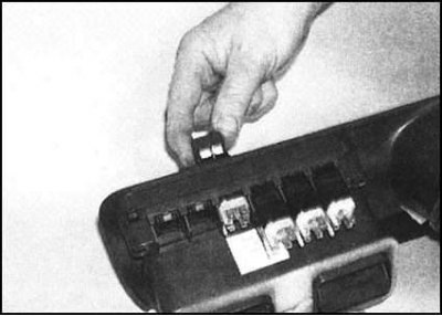
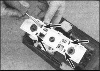
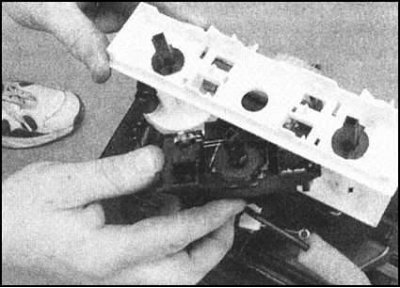
2. The assembly of each of the switches can be removed from the shield casing individually by releasing the corresponding latches.
3. When installing, make sure that the switch latches snap into place. A description of the procedure for installing the instrument panel is given in Section Removal and installation of the instrument panel.
The switch of management of functioning of the electric drive of external rear-view mirrors
1. Raise the inside door handle, then gently pry and remove the door trim panel.
2. Release the switch from the latches in the handle assembly and disconnect the electrical wiring from it.
3. Installation is carried out in the reverse order.
Assembly of switches for controlling the functioning of windows / heated front seats
1. Being careful not to damage the console trim, pry the switch assembly with a small screwdriver and remove it from its seat.
2. Disconnect the electrical wiring and remove the assembly from the vehicle.
3. Installation is carried out in the reverse order.
Interior door switches
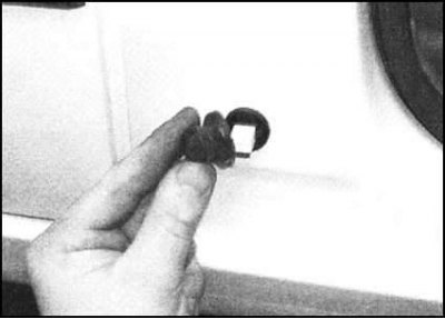
1. Open the door and remove the rubber protective boot from the switch assembly.
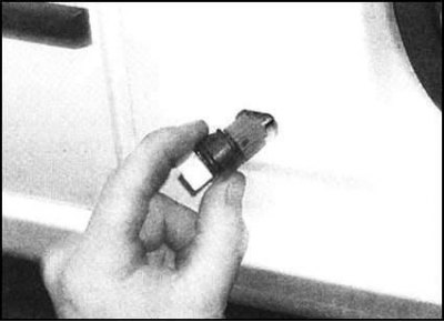
2. Release the latches and gently pry the switch out of the door post. Disconnect the wiring (see accompanying illustration). Glue the protruding piece of electrical wiring with the connector plug with adhesive tape so that it does not accidentally fall into the rack.
Note. If there is not enough slack in the wiring to allow the switch to be removed, remove the interior trim panels from the rack to gain access to the connector inside the latter.
3. Installation is carried out in the reverse order. Track reliability of landing of a rubber protective cover.
Luggage compartment light switch
1. Remove the tailgate lock assembly (see chapter Body and trim).
2. Disconnect the electrical connector and remove the interior lighting switch /
 |  |
3. Installation is carried out in the reverse order. Before installing the insulation film and interior trim panel on the door, check that the switch is working properly.
Brake light switch
see chapter Brake system.
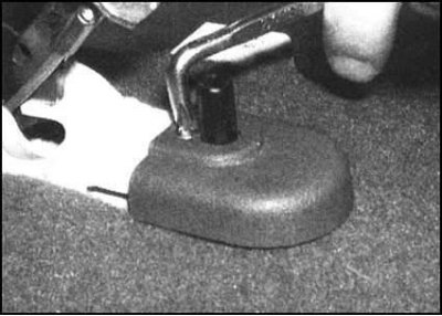
Parking brake lever switch
1. On suitably equipped models, remove the center console (see chapter Body and trim).
2. On models without a center console, pry up and remove the decorative cover from the parking brake lever.
3. Turn out the fixing screw and remove a decorative cover of the gauge-switch.
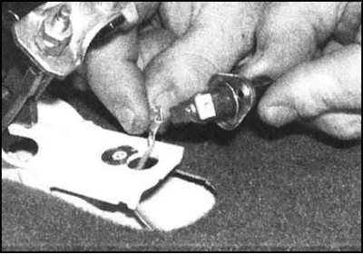
4. Remove the sensor-switch from its mounting socket and disconnect the electrical wiring from it.
5. Installation is carried out in the reverse order. Before reinstalling the center console/lever cover, check that the sensor-switch is functioning correctly.
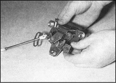
Heater fan speed selector switch
1. Remove heater/fan shroud assembly (see chapter Cooling, heating systems).
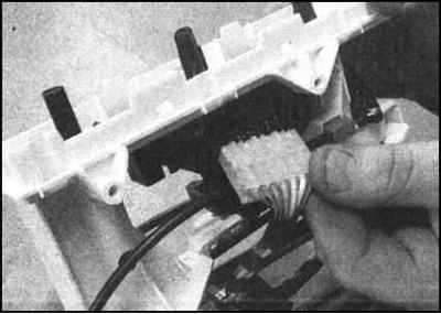
2. Disconnect the electrical wiring from the switch assembly.
3. Remembering the installation position of all components (cable ends are color coded), use pliers to release the latches and disconnect the drive cables from the fan motor base and heater control switch panel.
4. Release the backlight reflector from the front of the control switch panel.
5. Release the latches and remove the fan speed selection switch assembly from the panel.
 |  |
6. Installation is carried out in the reverse order. A description of the procedure for installing the heater/fan casing assembly is given in Chapter Cooling, heating systems.