Company vehicles Hyundai Company vehicles Kia Company vehicles Lada Company vehicles Mazda Company vehicles Mercedes-Benz Company vehicles Opel Company vehicles Mitsubishi
English Русский
Български
Беларускі
Український
Српски
Hrvatski
Română
Polski
Slovenský
Magyar
Articles   
Bookmark Contacts Sitemap
SkodaBook.ru


Fabia Rapid Octavia Superb Kodiaq Yeti Others
Favorit (1987-1994) Felicia (1994-2001)

Fuses, Relays and Circuit Breakers — General Information (Skoda Felicia)

  • Main
  • Skoda
  • Felicia (1994-2001)
  • Electrical equipment
  • Equipment and devices
  • Fuses, Relays and Circuit Breakers — General Information
0
Contents: Fuses ⬇ Electrical diagram of the relay ⬇ Direction indicator/hazard warning…⬇

Fuses


Most fuses are placed together with the relay in a special mounting block, installed under the instrument panel in the passenger footwell. Fuses for some additional systems (ABS, K/V) can be installed in separate holders, fixed in the left part of the engine compartment. On diesel models, fuses for the preheating system and the cooling fan can also be located in the engine compartment of the car.

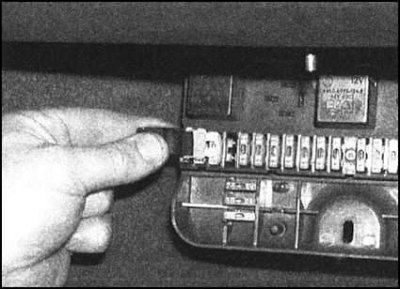
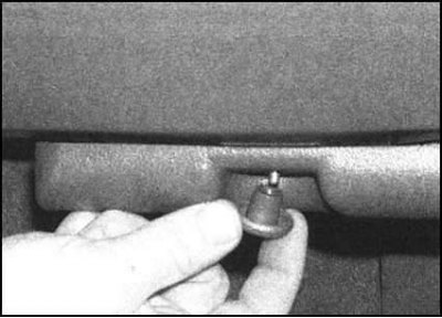
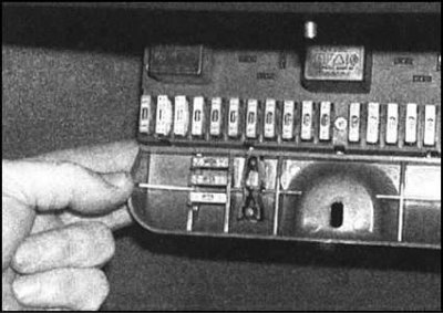
To gain access to the fuses, unscrew the fastening clip and, unfolding it like a book, release the mounting block from the instrument panel. The list of fuses is given in the last Section of this Chapter. To access the fuses located in the engine compartment, open the hood, release the clips and the cover from the corresponding holder.
Fuses, Relays and Circuit Breakers — General…


Fuses, Relays and Circuit Breakers — General…


To replace a fuse, first disconnect the…


To replace a fuse, first disconnect the corresponding circuit/turn off the ignition. Then grasp the body of the knocked-out fuse with special pliers fixed in the cover of the unit and, pulling it vertically upwards, remove it from the holder terminals. A blown fuse is easily identified by a melted or burnt conductive jumper.


Never replace a blown fuse with one rated for a higher rating (by current strength) loads. An extremely bad practice is to restore a failed fuse by short-circuiting its contacts using metal foil.

If the replacement fuse fails immediately after power is supplied to the circuit, then there is a short circuit in the circuit, the cause of which must be identified and eliminated. If the fuse being tested is used to protect several electrical circuits at the same time, try to identify the faulty circuit by switching on each of the circuits under control one by one, thereby eliminating those that are obviously serviceable.

Electrical diagram of the relay
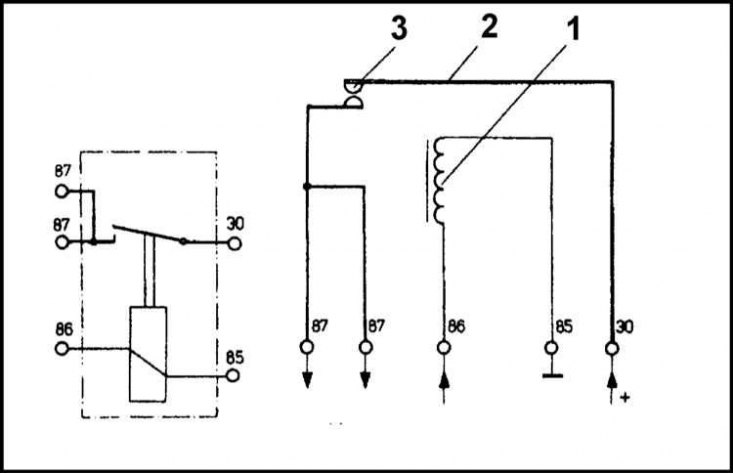


1 - Winding; 2 - Movable contact (anchor); 3 -…

1 - Winding; 2 - Movable contact (anchor); 3 - Contacts


A relay is an electromechanical switch used primarily in power circuits. The electrical circuit diagram of a typical relay design is shown in the illustration.

Most of the relays used in the vehicle are housed in the same mounting block as the fuses. Additional relays (type of diesel engine preheating system relay) located in the engine compartment.

To provide access to the relay, unscrew the fastening clamp and, unfolding it like a book, release the mounting block from the instrument panel.


If there is a suspicion that the failure of any of the electrical circuits is associated with the failure of its control relay, turn on the corresponding system - a serviceable relay should make a clearly audible click when power is supplied to it. If a click is heard, then the cause of the failure is a malfunction of the working component itself, or a failure of the electrical wiring. Otherwise, there is either a power supply failure, or the relay itself is faulty. The condition of the relay is checked by substituting a known good one in its place. It should not be forgotten that the external similarity of two relays does not necessarily guarantee the identity of their operating principle.

To replace a relay, first turn off the corresponding electrical circuit. Then the relay can be easily removed by pulling it out of the receiving socket. Install a new relay in place of the removed one, with the corresponding operating parameters.

Direction indicator/hazard warning flasher
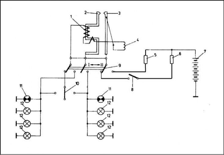


1 - Winding; 2 - Contact; 3 - Contact; 4 -…

1 - Winding; 2 - Contact; 3 - Contact; 4 - Thread; 5 - Fuse 15 A; 6 - Fuse 8 A; 7 - Battery; 8 - Ignition switch; 9 - Hazard warning switch; 10 - Direction indicator switch; 11 - Direction indicator/hazard warning lights; 12 - Direction indicator lamps


The connection diagram for the direction indicator/hazard warning flasher is shown in the illustration.
This article is available at russian, bulgarian, belarusian, ukrainian, serbian, croatian, romanian, polish, slovak, hungarian
Article verified: Ekaterina Blinova
Share with friends:
◀ Previous
Skoda Felicia: Equipment and devices
Next ►

Search for causes of electrical equipment failures
General information and precautions
Relays, Fuses and Lamps — Specifications
Removal and installation switches
Removal and installation the instrument panel
Removal and installation the speedometer drive cable
Removal and installation the cigarette lighter
Removal and installation the horn
Read similar articles on other Skoda models

➧ Checking the power supply circuit of gasoline engine injectors Skoda Fabia 1 (1999-2007)
➧ Colour coding of fuses Skoda Rapid 1 (2012-2022)
➧ Location of fuses and relays Skoda Octavia 1 (1996-2004)
➧ Fuses and relays Skoda Superb 2 (2008-2015)
➧ Relays and Fuses — location of fuse boxes (sa) in block e Skoda Kodiaq 1 (2016-2024)
➧ Fuses and relays Skoda Yeti (2009-2017)
Link to this article in various formats
Reviews and comments of visitors
No comments yet


Add two numbers: 43 + 10


Favorit (1987-1994) 
  • General information
  • Maintenance
  • Troubleshooting
  • Power unit
  • Engine in car
  • Engine overhaul
  • Cooling and heating
  • Fuel and exhaust system
  • Fuel injection system
  • Ignition system
  • Transmission
  • Clutch
  • Manual gearbox
  • Drive shafts
  • Chassis (running gear)
  • Brake system
  • Car suspension
  • Steering
  • Body and interior
  • Exterior (external elements)
  • Interior (salon)
  • Electrical equipment
  • Equipment and devices
  • Power devices
  • Electrical circuits
Felicia (1994-2001) 
  • General information
  • Introduction to guide
  • User manual
  • Maintenance (petrol)
  • Maintenance (diesel)
  • Power unit
  • Petrol engine 1.3 l
  • Petrol engine 1.6 l
  • Diesel engine
  • Engine overhaul
  • Cooling system
  • Fuel system (carburetor)
  • Central injection (SPFI)
  • Multipoint injection (MPFI)
  • Diesel power system
  • Decreased toxicity
  • Engine electrics
  • Transmission
  • Clutch
  • Car gearbox
  • Drive shafts
  • Chassis (running gear)
  • Brake system
  • Car suspension
  • Steering
  • Body and interior
  • Exterior (external elements)
  • Interior (salon)
  • Doors, locks and windows
  • Electrical equipment
  • Equipment and devices
  • Headlights and lighting
  • Electrical circuits
SkodaBook.ru © 2018–2026 | Mobile version | Articles on Skoda | Sitemap EN BG BY UA RS HR RO PL SK HU | Feedback | Site search | Bookmark
Fabia 1 (1999-2007) | Fabia 2 (2007-2014) | Rapid 1 (2012-2022) | Octavia 1 (1996-2004) | Octavia 3 (2013-2019) | Superb 2 (2008-2015) | Kodiaq 1 (2016-2024) | Yeti (2009-2017) | Favorit (1987-1994) | Felicia (1994-2001) |
By continuing to use the site, you agree to the use of cookies.