
Carburetor cover components
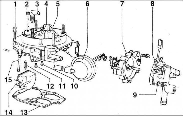
1 - Screw (7 Nm); 2 - Free running tube; 3 - Ventilation tube; 4 - Air damper; 5 - Econostat chamber II; 6 - Vacuum chamber of the additional starting device (Pulldown); 7 - Starting device; 8 - Semi-automatic starter cover
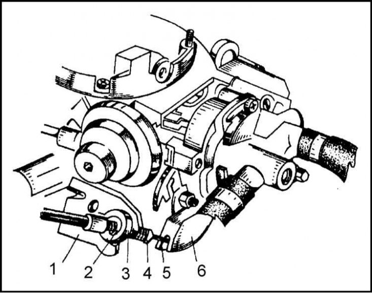
Carburetor Body Components
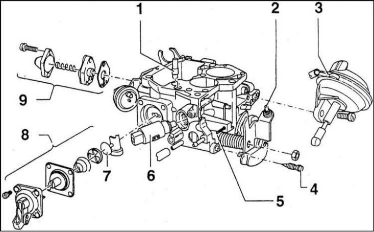
1 - Economizer tube; 2 - Screw for adjusting the speed of fast idle; 3 - Membrane throttle sensor II; 4 - Screw for adjusting the quality of the idle mixture; 5 - Screw for adjusting idle speed; 6 - E / m shut-off valve economizer forced idling (EPH); 7 - Inlet valve of the accelerator pump; 8 - Accelerator pump; 9 - Economizer
Fragment of the section of the float chamber
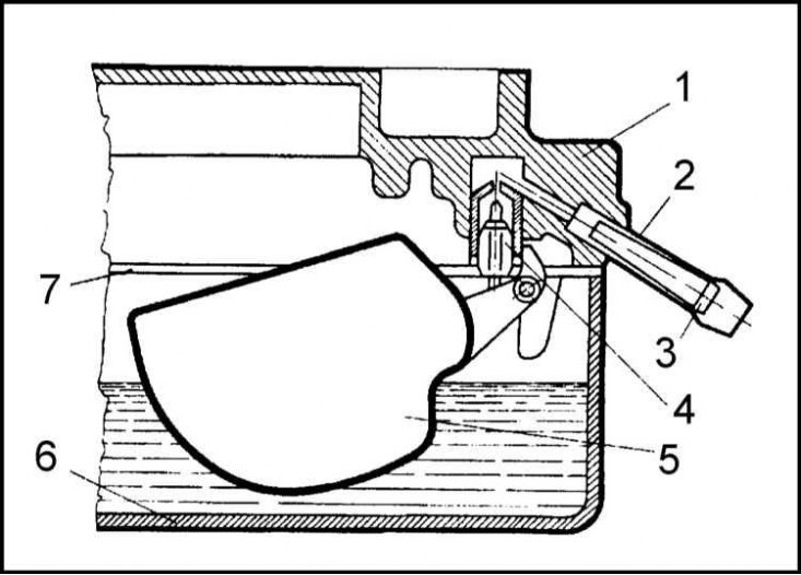
1 - Carburetor cover; 2 - Inlet pipe; 3 - Mesh filter element; 4 - Needle valve; 5 - float; 6 - Carburetor body; 7 - Sealing gasket
Design of the filter/return device
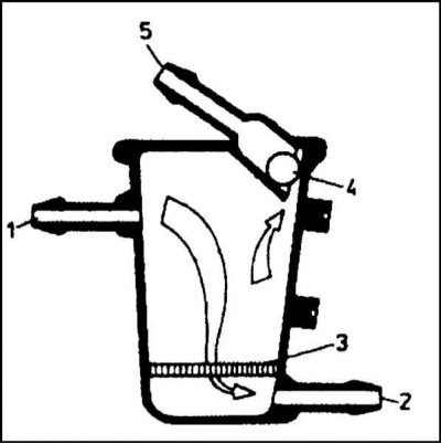
1 - Fuel supply fitting from the fuel pump; 2 - Fuel supply fitting to the carburetor; 3 - Mesh filter; 4 - Ball valve; 5 - Drain fitting
Accelerator pedal and throttle cable
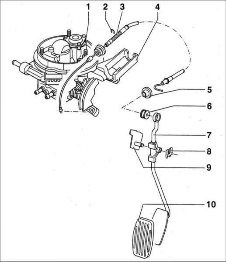
1 - Carburetor; 2 - Retaining ring; 3 - Throttle actuator cable; 4 - Bracket; 5 - Rubber sealing sleeve; 6 - Rubber bushing; 7 - Gas pedal; 8 - Retainer; 9 - Axis of the pedal; 10 - Rubber pedal pad
Attachment point for drive cable to throttle lever
1 - Nest of the latch of the landing of the tip of the cable; 2 - Throttle actuator lever; 3 - Throttle cable
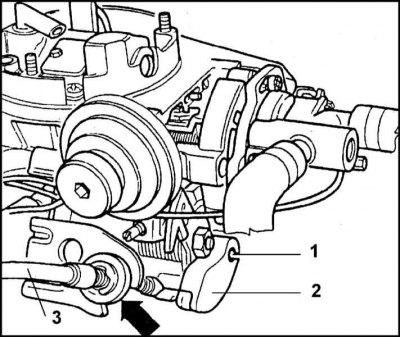
Engine idle speed adjustment
1 - Screw for adjusting idle speed; 2 - Stepped pulley; 3 - Screw for adjusting the position of the air damper of the semi-automatic start
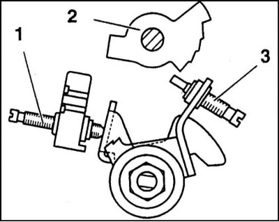
Throttle actuator free play adjustment
1 - Bracket; 2 - Retainer; 3 - Rubber washer; 4 - Rope sheath; 5 - Drive cable; 6 - Throttle actuator lever
Composition and design
The carburetor is designed to prepare an air-fuel mixture and dose it into the combustion chambers depending on the current load and engine speed.
The Pierburg 2E3 / Jikov 28-30 LEKR carburetor used to complete the considered car models is equipped with a semi-automatic starting system that provides reliable engine start in all temperature conditions typical for the middle lane, and also allows you to start driving immediately after a cold start. Among the factors determining the mode of operation of semi-automatic start-up factors are:
- a) Ambient temperature;
- b) Engine coolant temperature;
- c) Depth of depression in the intake manifold.
After starting the engine, the mixture is depleted in two stages, with the system functioning properly, the start is made on the first, maximum on the second attempt, even in frosty weather at an air temperature of -20°C.
The design of the carburetor is shown in the illustrations. The main components of the carburetor include the following devices:
- a) Semi-automatic starting device;
- b) Idle system providing stable idle speed of the engine (800÷850 per minute);
- c) Transition chamber system I, providing a smooth increase in engine speed when opening the throttle valve II;
- d) Air-fuel mixture enrichment system (econostat) at full load;
- e) Diaphragm accelerator pump with mechanical drive;
- f) Solenoid shut-off valve that shuts off the fuel supply to the carburetor after the ignition is turned off, as well as when the forced idle economizer is activated (EPH);
- g) A float chamber that maintains a predetermined fuel level in the carburetor.
A filter element is located under the needle valve of the float chamber, the mesh of which finely cleans the fuel supplied to the carburetor.
Inside the needle valve there is a small spring on which the ball rests, partially protruding outward. deforming, the spring dampens the jerks of the float lever when the car is moving fast. Thanks to this adjustment, the fuel level in the float chamber is kept constant.
The valve needle is coated with high-strength Viton compound, which is particularly durable. Thanks to this coating, a high tightness of the assembly is ensured. The needle valve is designed for approximately 150,000 km and does not require additional regular maintenance.
When the fuel level in the chamber drops, the float goes down and slightly opens the needle valve. At the same time, the necessary additional amount of fuel is pumped into the chamber. An increase in the amount of fuel causes the float to rise and automatically close the valve.
The carburetor is also equipped with an additional strainer. The filter assembly is installed at the inlet to the float chamber and is equipped with a ball valve that allows excess fuel to be diverted from the carburetor back to the fuel tank. In addition, fuel vapors are vented through the valve when a hot engine is turned off. The presence of the valve also avoids the ingress of fuel vapor into the carburetor when the engine is running in hot weather, which leads to a violation of the stability of the latter.
The carburetor is attached to the intake manifold with three M6x20 bolts through a rubber-metal sealing gasket that reliably seals the joint. The gasket is attached to the intake manifold with four hex head bolts.