



Cylinder head (front view)
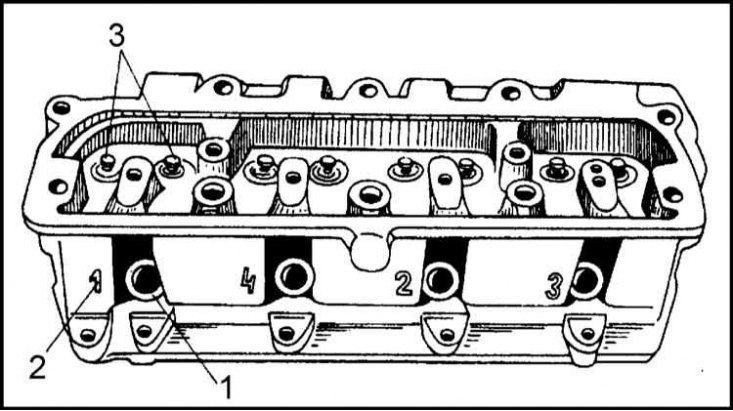
1 - Spark plug hole; 2 - Spark plug wire connection mark; 3 - Valve guide bushings
Cylinder head (rear view)
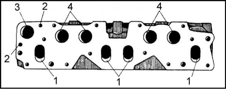
1 - Exhaust valve openings; 2 - inlet valve openings; 3 - Coolant outlet hole; 4 - Inlet valve openings
Cylinder head
The appearance of the cylinder head is shown in the illustration.
The cylinder head contains combustion chambers. Valve guide bushings are pressed into the aluminum casting of the head. The bushings are made of cast iron with 0.5% phosphorus added.
The seats of the intake and exhaust valves are pressed into the walls of the combustion chambers of the cylinder head (the inlet valve seat is larger in diameter).
The inlet and outlet channels are located on the same side of the head, which allows for preliminary heating of the air-fuel mixture in the inlet channels. The inlet channels have a round cross-section (Ø 25 mm) and are located above the outlet channels, which have an oval cross-section of 22x30 mm.
On the opposite side of the cylinder head there are threaded holes for installing spark plugs (M14x1.25). Next to the spark plug niches there are marks in the form of numbers from 1 to 4, indicating to which terminal of the ignition distributor cap the high-voltage wire of this spark plug should be connected.
The water galleries are connected to the outlet, near which the thermostat housing is installed, and to the inlet ports located in the upper part of the cylinder head, next to the combustion chambers.
The surface of the head mating with the block and the internal surfaces of the combustion chambers are subjected to careful mechanical treatment in compliance with the requirements for shape and cleanliness, allowing to maintain the same volumes of all combustion chambers and achieve an equal degree of compression in all cylinders. In addition, the treatment guarantees the tightness of the joints.
The cylinder head is secured to the block with ten M11 hexagonal-head bolts and four nuts screwed onto M8 studs. Seven bolts are 168 mm long, two are 183.5 mm long and one is 132.5 mm long. The bolt heads have a hexagonal recess for a 10 mm socket wrench.
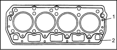
The cylinder head gasket is made of reinforced, asbestos-free material. Due to the low elasticity of the gasket, there is no need to tighten the head mounting bolts after the first thousand kilometers of mileage.
The head is closed from above with a cover, which is also cast from an aluminum alloy. The cylinder head cover is equipped with an oil filler neck, which is closed with a plastic plug. The tightness of the plug fit is ensured by equipping it with a rubber sealing ring 70x60 mm.
A rubber sealing gasket is installed between the cylinder head and its cover to prevent engine oil leakage.
Cylinder block
The cylinder block is the main supporting part of the power unit design. The block is made of lightweight aluminum alloy by die casting. The block weight is 13 kg.
At the bottom of the cylinder block are three bearings of the main journals of the crankshaft. The crankshaft has three main journals (so-called partial support crankshaft).
The main bearing caps are made of cast iron and, since they are not interchangeable, are marked with the appropriate numbers. On the second cap, on the outside, there is a threaded hole for attaching the oil intake of the oil pump.
The main bearing caps are fastened with M11 bolts, the required tightening force of which is 67÷75 Nm).
The cylinder block has channels for coolant, as well as channels for oil supply.
The thread in the holes in the block for the cylinder head mounting bolts starts 30 mm below the upper edge of the hole, which ensures better tightness of the joint of the units and reduces the concentration of casting stresses around the fasteners.
The oil pan is attached to the bottom of the block with nine M6 bolts.
Cylinder liners
The liners are made of grey cast iron with the addition of 0.5% phosphorus. The liners are installed in the cylinder bores in the block.
The outer surface of the sleeves is washed with coolant, i.e. these are so-called "wet" sleeves.
The working surfaces of the sleeves are subjected to honing with a high degree of precision and purity.
Each of the sleeves is equipped with two mounting belts, one of which is located on top, and the other is at a distance of about 2/3 of the length of the sleeve closer to the lower edge of the latter.
To ensure correct installation of the liners, the manufacturer produces copper ring adjusting washers with a thickness of 0.10, 0.12 and 0.14 mm. By selecting adjusting washers, the liners protrude from the combustion chamber to a strictly specified height. The liners should protrude above the block surface by 0.07÷0.13 mm.
The sleeves are manufactured with a nominal internal diameter of 75.5 mm and are grouped into three tolerance classes: A, B and C (see Specifications). The class of the cartridge case is applied to its side surface.
The manufacturer does not provide for the possibility of using repair size sleeves.
Gas distribution mechanism
Timing belt operation diagram
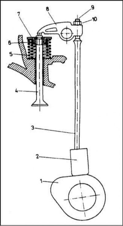
1 - Camshaft cam; 2 - Pusher; 3 - Push rod; 4 - Valve; 5 - External spring; 6 - Inner spring; 7 - Plate; 8 - Valve drive rocker arm; 9 - Adjusting screw; 10 - Lock nut
The valve timing mechanism (VDM) controls the intake of fresh air-fuel mixture into the cylinders at the appropriate moments and the release of exhaust gases from the combustion chambers.
The engine belongs to the OHV family of units, i.e. it has an overhead valve arrangement. The camshaft is correspondingly located at the bottom. The mechanism operation diagram is presented in the accompanying illustration.
The camshaft cams, rotating, lift the pushers, the movement of which is transmitted through the rods to the rocker arms. The rocker arms are mounted on a separate axis, fixed with brackets on the cylinder head. Performing oscillatory movements, the rocker arms directly affect the valve stems, forcing the latter to open and close at the right moments in time.
Each valve is pressed against its seat by two springs (internal and external). The valves move in guide bushings pressed into the cylinder head.
The camshaft, which controls the operation of the valves by means of eight eccentric cams, is made of high-quality steel. The cams are hardened by high-frequency current. The camshaft is installed in three plain bearings machined directly into the cylinder block casting. In order to facilitate the installation of the shaft in the bearings, all three of them have different diameters. The first journal on the timing drive side has the largest diameter, the middle one is slightly smaller, and finally the last one (closest to the flywheel), - the smallest. Camshafts are produced only with journals of the nominal size (see Specifications).
Each pair of cams controls the opening and closing of the valves of one cylinder. The misalignment of the working projections (lifts) of the cams determines the moments (angles relative to TDC) opening and closing of valves (see Specifications at the beginning of this Chapter).
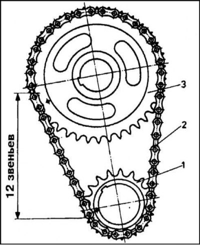
The leading sprocket of the timing chain is installed on the front crankshaft journal. The driven sprocket is on the distribution journal. The sprockets are tensioned on the shaft journals, blocked from turning by segment keys and pressed by bolts screwed into the ends of the journals.
On the camshaft, in addition to the driven sprocket, there is also a gear for driving the oil pump and the ignition distributor. In view of the above, the correct mutual position of the sprockets is of vital importance, since the installation of the valve timing depends on it.
The correct position of the camshaft relative to the crankshaft is achieved by appropriately placing the marks on both sprockets. The marks are made in the form of shallow holes and should be spaced from each other at a distance equal to 12 chain links. In this case, the link located above the mark on the leading sprocket is considered the first, and above the mark on the driven sprocket - the twelfth.
[Information copied from the resource: www.SKODABOOK.ru]
The pushers are made in the form of an open cylinder. One side of the pusher bottom, interacting with the cam of the tearer, is flat, on the other there is a spherical recess, into which the end of the pusher rod fits. The working surface of the pusher is made very hard.
The pushrods transmit movement to the rocker arms of the valve drive. The pushrods are forged from a steel rod with hardened and polished ends. The upper end of the pushrod has the shape of a bell, while the lower end is made in the form of a slightly expanded half-sphere. The pushrods of the intake and exhaust valves have the same length.
Rocker arms are used to transmit movement from the pushrods to the valve stems. The surface of the rocker arm that contacts the valve stem is forged. The rocker arms of the intake and exhaust valves differ in shape, but are mounted on a common axis.
The rocker arm facing the push rod is equipped with a threaded hole into which an adjusting screw is screwed, by turning which the valve clearance can be adjusted. The head of the adjusting screw is hardened, and a flat lock nut is provided for locking.
In the middle part of the rocker arm, a small channel sensor-switch is drilled. Through one channel, oil is supplied to lubricate the rocker arm axis, through the second, oil is injected between the turns of the valve springs in the direction of the valve stem.
The valves open and close the inlet and outlet channels of the combustion chambers, which allows the cylinders to be filled with fresh air-fuel mixture at the right time and exhaust gases to be removed from them.
The valves are made of special steel. The valve consists of a stem and a plate. The conical part of the plate, adjacent to the valve seat and called the sealing surface, is beveled at an angle of 45° 30'±5' (in Czech-made valves), or 44° 50'±20' (in imported valves).
The valve stem is made of steel, the plate is made of AKMV alloy, and the sealing surface of the plate is additionally coated with a layer of a special Stelit F alloy, which protects it from the destructive effects of gases heated to very high temperatures.
The intake valves are made of heat-resistant steel, the sealing surface of the plate is formed by forging. The valve stems are chrome plated, which reduces the friction component and prevents the possibility of jamming in the guide bushings.
The materials used, subject to the frequency of valve clearance adjustments, guarantee the proper functioning of the valves for 120,000 km of mileage.
The diameter of the intake valve plate is 34 mm, the exhaust valve plate is 30 mm. This is done in order to minimize the area in contact with hot exhaust gases. Grooves for installing split lock crackers are provided at the end of the valve stems.
Split locks consist of a double conical bushing - crackers, which are fixed on the rod by the upper plate of springs. The springs press the valve plates with sealing surfaces to the seats, thus ensuring proper tightness of the combustion chambers.
The springs are made of special steel. Each valve is equipped with two cylindrical springs: external and internal. The use of two springs instead of one is due to the fact that, due to the limited free space, one spring will not be able to provide the necessary force to press the plate to the seat. The springs are twisted in opposite directions, which eliminates the risk of intertwining their coils in case of damage.
The height of the springs is selected in such a way that at maximum compression (with the valve open) the turns did not touch each other.
The lower coils of the springs rest against the cylinder head surface through a steel washer. The use of such washers turned out to be a forced measure, since the cylinder head is made of a soft aluminum alloy.
The upper ends of the spring rest against a plate fixed to the end of the valve stem. The nominal parameters of the valve springs are given in Specifications.
The valve guide bushings are made of cast iron. The task of the bushings is to constantly maintain the valve in the correct position relative to the seat, ensure its free movement and remove excess heat. The bushings are pressed into the cylinder head. Bushings of repair sizes are not produced.
The bushings are fitted with oil-deflecting caps. On the inside of the cap there is a ring-shaped projection that collects excess oil from the valve stem. A small ring spring is installed in the upper part of the cap, ensuring its constant pressure against the stem. The use of oil-deflecting caps reduces the consumption of engine oil associated with its penetration into the combustion chambers. Accordingly, the level of hydrocarbon emissions into the atmosphere is reduced.
Valve seats ensure the tightness of valve closure and heat dissipation from the latter. The seats are made of special cast iron, have the shape of a rectangular ring and are pressed into the cylinder head body under very high pressure. The material used to manufacture the seats allows the use of both unleaded and leaded gasoline for refueling the car.