
Cross section of the engine
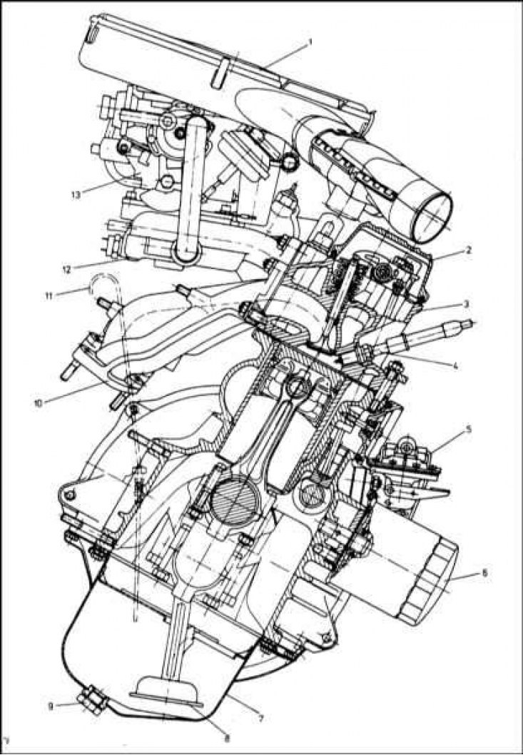
1 - Air filter housing; 2 - Cylinder head cover; 3 - Cylinder head; 4 - spark plug; 5 - Fuel pump; 6 - Oil filter; 7 - Oil pan; 8 - Oil intake with strainer; 9 - Drain plug; 10 - Exhaust manifold; 11 - Full flow oil filter; 12 - Inlet pipeline; 13 - Carburetor
Longitudinal section of the engine
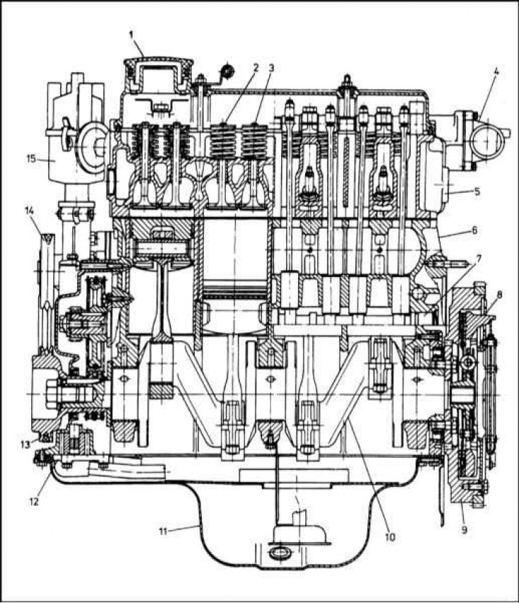
1 - Filler cap; 2 - Inlet valve; 3 - Exhaust valve; 4 - Thermostat housing; 5 - Cylinder head; 6 - Cylinder block; 7 - Camshaft; 8 - Clutch assembly; 9 - Flywheel; 10 - Crankshaft; 11 - Oil pan; 12 - Oil pump; 13 - Crankshaft pulley; 14 - Water pump pulley; 15 - Ignition distributor
Rules for using the material Chapters
This Part of the Chapter is devoted to the repair of a 1.3 liter gasoline engine that is not related to removing it from the car (in situ).
The description of most of the procedures under consideration is based on the assumption that the power unit remains in its regular place in the engine compartment of the car. In view of the above, if the engine has already been removed and installed on a workbench or mounting stand, many of the described steps should be omitted.
Note that despite the physical possibility of in situ repair of such components as connecting rod and piston groups, this kind of work is usually carried out after disassembling the engine due to the need for some auxiliary procedures, not to mention the requirements for maintaining the cleanliness of parts and absolute patency of oil flows.
General description of the engine
The engine in question belongs to the family of 4-cylinder gasoline engines with in-line cylinders and overhead valves (OHV). Cross and longitudinal sections of the engine are shown in the illustrations. The engine is mounted transversely at the front of the vehicle and tilted forward at an angle of 20°. The transmission and clutch assemblies are located on the left side of the power unit.
Engines have two main modifications: with a low compression ratio (type 135) and high compression (type 136), which also differ in the design of the pistons (on the bottoms of the pistons of engines of the 135th type, unlike the 136th, samples are provided) and camshafts. The rest of the engines are identical. Visually, the engines can be distinguished from one another by the color of the emblem with the Skoda logo located on the front wall of the cylinder head. Type 135 engines use a colorless emblem, while type 136 engines have a yellow emblem.
Cylinder block, head and head cover are cast aluminum alloy. The lower part of the cylinders is lined with cast iron liners. The bases of the sleeves are equipped with seals to prevent coolant from penetrating into the oil pan.
The crankshaft is mounted in three main bearings. The flywheel with the clutch assembly is attached to the flange on the left end of the shaft. The front end of the crankshaft is equipped with a sprocket for installing a two-row camshaft drive chain. The main and connecting rod bearings are of a split design and equipped with two liners. A bronze bushing is pressed into the upper head of the connecting rod, deployed to fit the piston pin.
The right end of the camshaft is equipped with a helical gear for the ignition distributor drive. The oil pump is also driven from the camshaft through the distributor axis.
The forced lubrication system of the engine is organized by means of a gear pump, which takes oil from the oil pan through an oil intake equipped with a strainer and supplies it to the internal components of the engine, after driving it through a full-flow oil filter of a replaceable type, installed outside in front of the cylinder block.
Despite the fact that the engine is not high-speed and does not have a lot of power, it provides the car with quite decent dynamic characteristics.
Due to the fact that the engine is not overloaded, provided that high-quality oil and fuel are used, it is characterized by increased reliability and durability.
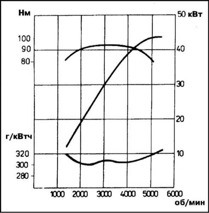
The illustration shows power and torque curves, as well as fuel consumption, depending on the speed of the crankshaft of a carbureted engine.
List of repair procedures that do not require removing the engine from the vehicle
The following are engine repair and maintenance procedures that can be performed in situ:
- a) Removal and installation of the auxiliary drive belt;
- b) Removal and installation of a cover of a head of cylinders;
- c) Removal and installation of rocker arm assembly;
- d) Removal and installation of the cylinder head;
- e) Removal and installation of the timing chain cover;
- f) Removal and installation of the timing chain with sprockets;
- g) Removal and installation of the oil cooler;
- h) Removal and installation of the oil pump;
- i) Removal and installation of the oil pan;
- j) Decarbonization of the cylinder head and pistons;
- k) Replacement of crankshaft seals;
- l) Removal, condition check and installation of a flywheel;
- m) Checking the condition and replacing the suspension mounts of the power unit;