



Contents: Cylinder block ⬇ Crankshaft ⬇ Connecting rod and piston group ⬇ Cylinder head and valve timing ⬇ Water pump ⬇ Intake manifold and exhaust manifold ⬇
Cylinder block and its internal components
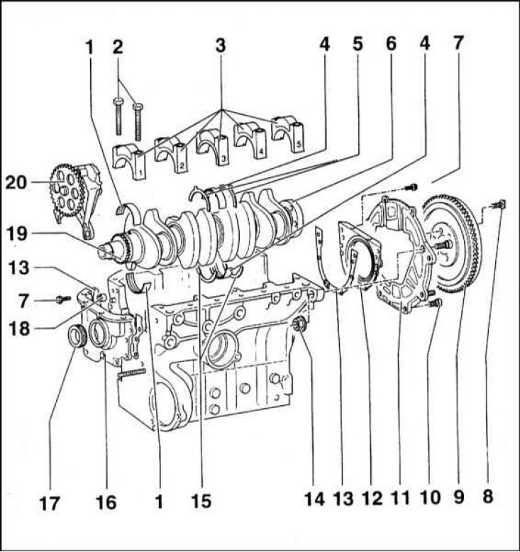
1 - Main bearing shell; 2 - Main bearing cap mounting bolts; 3 - Main bearing caps; 4 - Third (thrust) main bearing shells; 5 - Lower thrust half rings; 6 - Flywheel mounting flange; 7 - Flywheel mounting bolt; 8 - Flywheel mounting bolt; 9 - Flywheel; 10 - Rear cover mounting bolt; 11 - Back cover; 12 - Oil seal holder; 13 - Sealing gasket; 14 - Self-locking nut; 15 - Lower thrust half rings; 16 - Front cover; 17 - Front oil seal; 18 - Mounting sleeve; 19 - Oil pump drive gear; 20 - Oil pump
Connecting rod and piston assembly
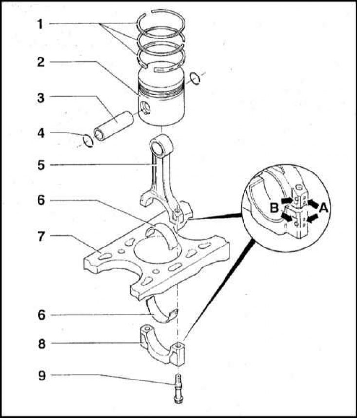
1 - Piston rings; 2 - Piston; 3 - Piston pin; 4 - Retaining ring; 5 - Connecting rod; 6 - Inserts; 7 - Cylinder block; 8 - Connecting rod lower head cover; 9 - Cover mounting bolt
Cylinder head and valve train components
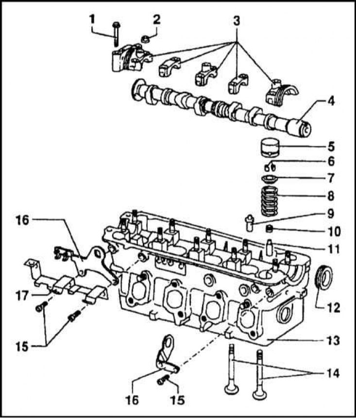
1 — Bolt for fastening the cover of the first support of the camshaft; 2 - Mounting stud nut; 3 - Camshaft bearing caps; 4 - Camshaft; 5 - Hydraulic pusher; 6 - Split lock crackers; 7 - Valve spring plate; 8 - Valve spring; 9 - Guide bushing (repair); 10 - Oil deflector cap; 11 - Guide bushing; 12 - Seal; 13 - Head casting; 14 - Valves; 15 - Bolts; 16 - Spring; 17 - Bracket for high-voltage wires
Hydraulic tappet operation diagram
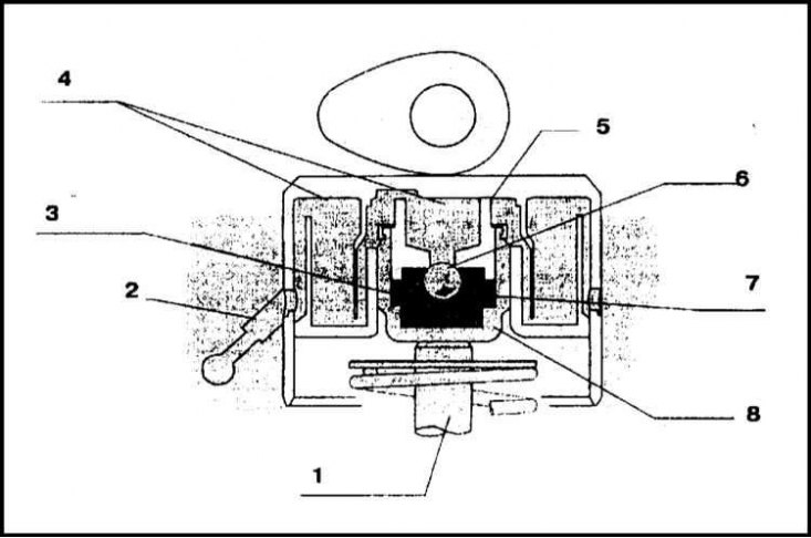
1 - Valve stem; 2 - Oil supply; 3 - Oil chamber; 4 - Low oil pressure; 5 - Piston; 6 - Ball valve; 7 - Spring; 8 - Plunger body
Timing drive diagram
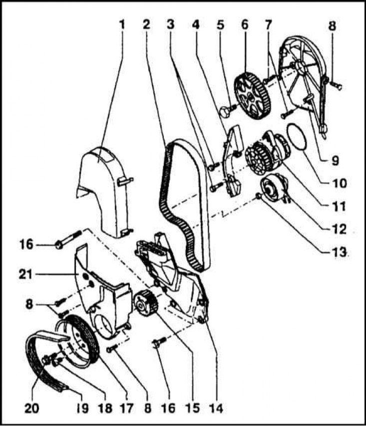
1 - Top cover; 2 - Toothed belt; 3 - Bolts; 4 - Belt shield in the area of the water pump; 5 - Bolt; 6 - Timing belt of the camshaft; 7 - Bolts; 8 - Bolts; 9 - Inner cover; 10 - Sealing ring; 11 - Water pump; 12 - Tension roller; 13 - Nut; 14 - Lid; 15 - Crankshaft gear; 16 - Bolt; 17 - Bolt; 19 - Multi-rib auxiliary drive belt; 20 - Bolt; 21 - Bottom cover
Cylinder block
The cylinder block is cast from cast iron. The general appearance and installation order of the cylinder block components are shown in the accompanying illustration. The cylinders are machined directly in the block body. Five beds of the crankshaft main bearings are made in the lower part of the block. The bearing caps are fastened to the block with special M10x65 bolts. Washers under the bolt heads are not installed.
The axial play of the crankshaft is controlled by thrust half rings installed on the third main bearing.
Crankshaft
The crankshaft is forged from steel and consists of five main and four connecting rod journals. The oil pump drive gear is fixed on the front journal of the shaft and a groove is provided for installing a segment key for the seat of the timing belt toothed wheel. A flange for installing a flywheel is equipped on the rear end of the shaft.
Connecting rod and piston group
Forged connecting rods have an I-section and a straight cut of the lower head. A bronze bushing is pressed into the upper head, which is then machined to the required diameter (17.6 mm). The lower head is cut in the middle, and then machined to a diameter of 50.6 + 0.01 (without inserts). The correct relative position of the connecting rod cap and connecting rod bearing liners is indicated by special marks. In addition, the cylinder number to which this connecting rod corresponds is also stamped on the head. The connecting rod bearing cap is attached to the lower head with M8x1 TORX bolts. During major repairs, it is customary to replace the connecting rod bearing cap bolts. The components of the connecting rod and piston assembly are shown in the illustration.
The pistons are cast from an aluminum alloy and have a concave bottom, the cavity of which partially forms the volume of the combustion chamber. When installing the piston, the mark on the bottom should be turned towards the location of the timing drive. The piston pin, which has a floating fit, is fixed in the assembly with two retaining rings. When seated on the connecting rod, the piston is heated to 60°C, after which the piston pin is inserted into it. Two compression rings and one oil scraper ring are installed on each piston.
Cylinder head and valve timing
The cylinder head contains in-line valves. The layout of the valve mechanism components in the head is shown in the illustration.
The cylinder head is attached to the block with ten special M11x1.5 TORX bolts. The head sealing gasket has a metal edging of the holes for the cylinders, and is covered with a silicone sealing layer along the perimeter. The correct position of the gasket on the block is ensured by two installation pins seated in the mating surface of the cylinder block.
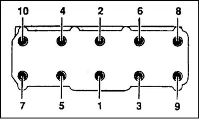
The tightening sequence of the cylinder head bolts is shown in the illustration.
The inlet and outlet channels are located on different sides of the head. Valve seats and guide bushings are pressed into the head body, and the camshaft supports are also formed. The camshaft bearing caps are secured in the head with M7 bolts. Seals are seated inside the outer bearing housings.
The valves are driven directly from the camshaft through tappets equipped with hydraulic compensators. The hydraulic compensators provide clearance-free valve drive. The hydraulic tappet operation diagram is shown in the illustration.
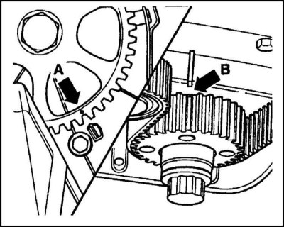
The timing gear is attached to the camshaft with an M14x1.5x47 bolt. The timing drive is performed by a belt transmission based on the CR Power 137STD8-19 toothed belt. The belt tension force is provided by a tension roller, which simultaneously increases the pulley coverage angle. When installing the toothed belt, it is necessary to achieve alignment of the installation marks. After installing the belt, it is necessary to turn the crankshaft several revolutions and again check the correct alignment of the marks.
The belt tension is adjusted automatically by a hydraulic tensioner. The timing drive diagram is shown in the illustration.
Water pump
The non-separable centrifugal water pump is attached to the cylinder block with two M8 bolts. The connection is sealed with a rubber sealing ring. The pump is driven by a toothed timing belt. In case of failure, the pump assembly is replaced.
Intake manifold and exhaust manifold
The intake manifold is made of plastic and is divided into four channels that connect to the intake ports of the cylinder head. The joint is sealed with a sealing ring. The intake manifold contains a flow meter and intake air temperature sensors, as well as an air thermostat. A fuel vapor recovery system tube is connected to the manifold from the outside.
The exhaust manifold is mounted on studs and is secured to the block using M8 nuts. A metal-reinforced sealing gasket is installed between the manifold and the head. When installing the exhaust manifold on the engine, the gasket and mounting nuts must be replaced.