
General information
Before proceeding with the procedure, it is necessary to immobilize the engine and the car:
- a) Disconnect the negative cable from the battery.
- b) Chock the rear wheels of the vehicle and apply the parking brake. Move the manual transmission control lever to the neutral position.
Note. If your vehicle's stereo system is equipped with a security device, make sure you have the correct code to activate the audio system before disconnecting the battery.
Tensioner
Removing
1. Bring the piston of the first cylinder to the TDC position of the end of the compression stroke (see Section Bringing the piston of the first cylinder to the top dead center position (TDC) end of compression stroke).
2. Separate the right power unit support, then remove the accessory drive belt, crankshaft pulley, and upper and lower timing belt covers (see Section Removal and installation of the timing belt and its covers).
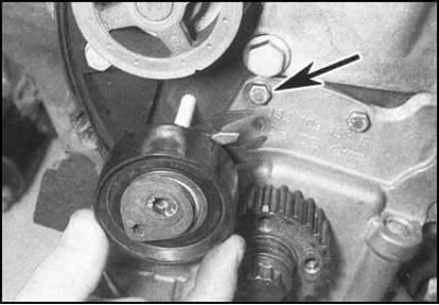
3. Loosen the tensioner pulley hub locknut.
4. Give a counternut and remove a tensioner from a fixing hairpin.
Examination
Thoroughly clean the tensioner without using any solvents to avoid contamination of the bearing. Turning the pulley by the hub manually, make sure that there are no jerks or jamming points. The presence of play indicates the wear of the assembly and the need to replace it.
Installation
1. Put the roller on the hairpin. The tensioner base plate should fit with a U-notch over the bolt. Lightly tighten the locknut.
2. Tension the timing belt (see Section Removal and installation of the timing belt and its covers).
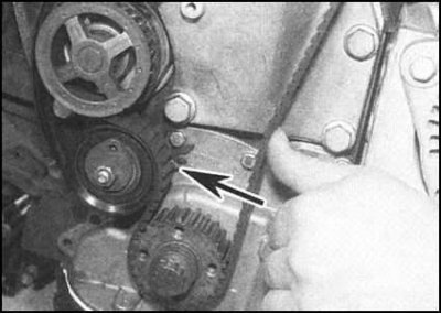
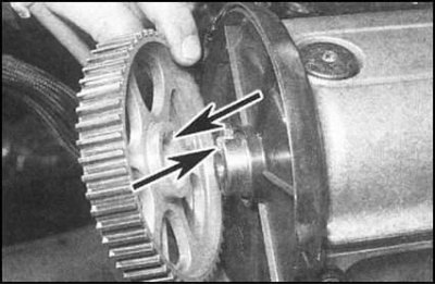
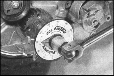
3. Check the correct functioning of the tensioner, for which firmly press the belt with your thumb in the area in the middle between the gears of the crankshaft and camshafts, the sliding pointer protruding from under the roller will move away from the mounting groove on the assembly base plate.
4. When the belt is released, the pointer should return to its original position, again aligned with the groove. If the pointer is jammed, the tensioner must be replaced.
5. Replace all removed components (see Section Removal and installation of the timing belt and its covers).
6. Upon completion of the assembly, check the correctness of the ignition timing (see chapter Engine electrical equipment).
Camshaft gear
Removing
1. Remove the timing belt covers and bring the piston of the first cylinder to the TDC position of the end of the compression stroke. After releasing the tensioner locknut, loosen the belt and remove it from the camshaft gear.
Attention! To avoid damage to cylinder head components resulting from accidental movement of the crankshaft during the removal/installation of the camshaft sprocket, the compilers of this manual recommend turning the shaft a couple of degrees back from TDC. Remember to return the engine to top dead center before putting on the belt.
2. Before giving away the fixing bolt, care should be taken to block the camshaft gear. Use the simplest fork, made from two pieces of metal strip and three nuts and bolts. One of the bolts acts as the axis of the tool fork, the other two are attached to the sprocket.
3. Having reliably blocked a cogwheel, give a fixing bolt.
4. Remove the gear wheel from the camshaft stub.
5. After removing the wheel, immediately check the camshaft oil seal for signs of leakage. If necessary, replace the seal (see Section Camshaft oil seal replacement).
6. Thoroughly wipe the mating surfaces of the gear and shaft journal.
Assembly
1. Put the gear on the camshaft stub (take care to align the keyway with the key).

2. With the gear wheel locked, tighten the bolt to the required torque in several steps.
3. Make sure the engine is at TDC (see Section Bringing the piston of the first cylinder to the top dead center position (TDC) end of compression stroke), then install the toothed belt and adjust its tension (see Section Removal and installation of the timing belt and its covers). Install all removed parts and connect the negative cable to the battery.
Crankshaft gear
Removing
1. Remove timing belt covers (see Section Removal and installation of the timing belt and its covers) and bring the piston of the first cylinder to the TDC position of the end of the compression stroke.
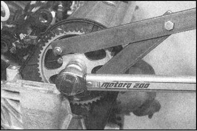
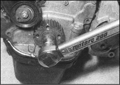
2. Block the crankshaft from turning. Blocking can be done using a special Skoda branded tool, or by jamming the flywheel ring gear through the hole for installing the starter (the procedure for removing the starter is described in Chapter Engine electrical equipment). Release a bolt of fastening of a cogwheel.
3. Blocking the engine from turning (see previous paragraph), loosen the crankshaft gear bolt (don't turn it out yet).
4. Make sure the engine is at TDC (see Section Bringing the piston of the first cylinder to the top dead center position (TDC) end of compression stroke), then loosen the tensioner locknut and loosen the timing belt tension. Carefully remove the belt from the crankshaft gear.
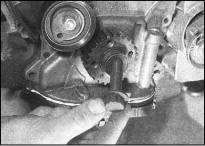
5. Turn out a bolt and remove a cogwheel.
 | 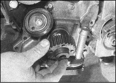 |
6. After removing the gear wheel, check the shaft seal, if there are signs of leakage, replace the defective seal (see Section Replacing the crankshaft seals).
7. Thoroughly wipe the mating surfaces of the gear and crankshaft trunnion.
Assembly
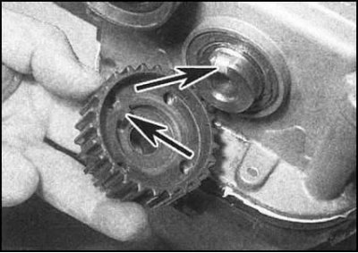
1. With the hub tooth aligned with the trunnion keyway, install the wheel in place. After lightly lubricating the threads, screw in a new mounting bolt and tighten it only by hand so far.
Note. The final tightening of the bolt is made after installing the timing belt. The tightening force is large enough to eliminate the risk of accidental turning of the shaft with the inevitable removal of the engine from the TDC position.
2. Make sure the engine is at TDC (see Section Bringing the piston of the first cylinder to the top dead center position (TDC) end of compression stroke), then install the timing belt and adjust its tension (see Section Removal and installation of the timing belt and its covers).
3. After blocking the crankshaft from turning, tighten the crankshaft gear bolt in several stages with the required force.
 |  |
4. In reverse order of removal, install the remaining components and connect the negative cable to the battery.
Water pump toothed belt
The gear wheel is built into the pump assembly and is not individually removed. The pump procedure is described in Chapter Cooling, heating systems.