
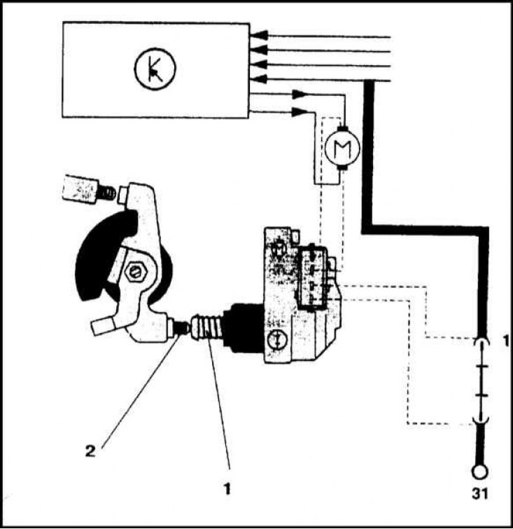
Wiring Diagram of Bosch Mono-Motronic System Components
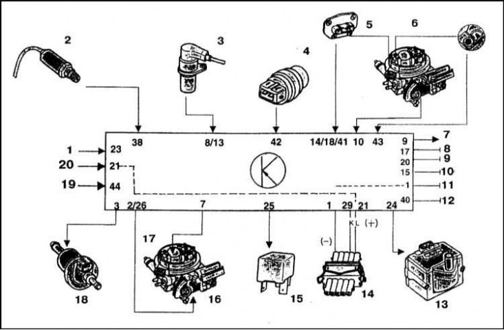
1 - From terminal 15 of the ignition switch; 2 - λ probe; 3 - Crankshaft speed sensor; 4 - Coolant temperature sensor; 5 - Throttle position sensor (TPS); 6 - Intake air temperature sensor (IAT); 7 - Output signal to the tachometer; 8 - Grounding the speed sensor; 9 - ECU ground; 10 - Grounding of the λ-probe; 11 - Grounding of the limit sensor-switch; 12 - ECU ground; 13 - Block of the ignition system; 14 - Diagnostic connector; 15 - Fuel pump relay; 16 - Stepper motor for throttle position control; 17 - Fuel injection injector; 18 - Valve of the fuel vapor recovery system; 19 - Control signal from λ-probe; 20 - From terminal 30 of the diagnostic connector
Upper Throttle Body Components
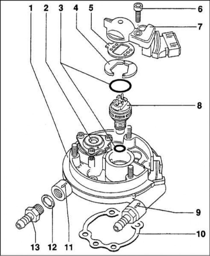
1 - Upper section of the throttle body; 2 - Fuel pressure regulator; 3 - O-ring; 4 - Mounting washer (not installed on all models); 5 - Sealing gasket; 6 - Screw for fastening the injection injector / IAT sensor; 7 - IAT sensor; 8 - Fuel injection injector; 9 - Union connection of the fuel supply line; 10 - Sealing gasket; 11 - Union connection of the fuel return line; 12 - Sealing washer; 13 - Fuel hose fitting
Note. See the warnings in Section General information and precautions.
The connection diagram of the components of the Bosch Mono-Motronic system is shown in the illustration.
Throttle body
Removing
1. Remove the air cleaner housing assembly (see Section Removing and installing the air cleaner assembly).
2. Relieve residual pressure in the supply system (see Section Release of residual pressure in the power system), then disconnect the negative cable from the battery.
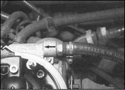
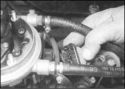
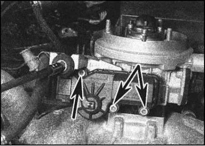
3. Disconnect the lines from the fittings on the wall of the throttle body. Mark the hoses according to the actual direction of fuel flow (see arrows in illustrations).
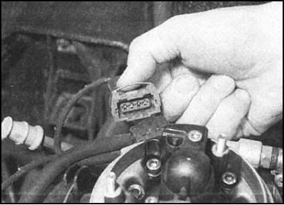
4. Disunite electric sockets on cases of a throttle. Label the wiring harnesses accordingly.
5. Disconnect the accelerator cable from the throttle body (see Section Removing, installing and adjusting the accelerator cable).
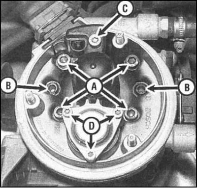
6. Turn out through bolts (A) attaching the throttle body to the intake manifold. Remove the throttle bodies from the pipeline and remove the gasket (if provided). Without real need, you should not dismember the throttle body - its halves are attached to each other by means of internal through bolts (IN). If such dismemberment is made, do not forget to replace a sealing lining.
Installation
Installation is in the reverse order. Do not forget to replace the seals and make sure the fasteners are securely tightened. Finally, adjust the tension of the accelerator cable (see Section Removing, installing and adjusting the accelerator cable).
Fuel Injector
Removing
1. Remove the air cleaner cover (see Section Removing and installing the air cleaner assembly).
2. Relieve residual pressure in the supply system (see Section Release of residual pressure in the power system), then disconnect the negative cable from the battery.
3. Disconnect the electrical wiring from the injection injector.
4. Remove the screw and remove the injector cap/intake air temperature sensor cover (IAT). Remove the gasket.
5. Remove the fixing washer (if provided), then remove the injector from the throttle body. Remove sealing rings.
6. Using a universal tester, measure the electrical resistance of the injector, compare the measurement result with the requirements Specifications.
Installation
Installation is in the reverse order. Don't forget to replace the o-rings and gaskets. Lubricate the threads of the fixing screws with a suitable sealant before installation. All fasteners are tightened with the required force.
Intake air temperature sensor (IAT)
The IAT sensor is mounted in the fuel injector cap, the removal and installation procedures for which are described in the previous subsection. Based on the information received from the sensor, the ECU adjusts the amount of fuel injected by the injector. In the event of a sensor failure, the ECU switches the system into emergency operation mode, generating a control signal corresponding to an air temperature of 20°C. in this case, there may be problems with starting the engine and the stability of its speed in the warm-up mode.
Fuel pressure control
Removing
1. If there is no confidence in the correct functioning of the regulator, you should disassemble the unit, then check it for signs of contamination and the integrity of the internal components.
Note. Skoda insists that in the event of a failure of the pressure regulator, the entire upper half of the throttle body assembly should be replaced. Consult a service station.
2. Remove the air cleaner cover (see Section Removing and installing the air cleaner assembly).
3. Relieve residual pressure in the supply system (see Section Release of residual pressure in the power system), then disconnect the negative cable from the battery.
4. Turn out the fixing screw and remove a cover of an injection injector/sensor IAT.
5. Remove the three TORX mounting screws and remove the fuel pressure regulator support frame.
6. Remove the top cover, spring and diaphragm.
7. Thoroughly wipe the components and check the diaphragm for cracks or other mechanical damage.
Installation
Installation is in the reverse order.
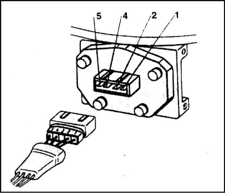
Throttle position module
Removing
1 - Limit switch contacts; 2 - Throttle actuator lever
1. Disconnect the negative cable from the battery. Remove the air cleaner cover (see Section Removing and installing the air cleaner assembly). A limit switch and a throttle actuator stepper motor are installed in the lower part of the throttle body and provide an enrichment of the air-fuel mixture during engine start and warm-up, as well as shutting off the fuel supply during engine braking.
2. Disconnect the accelerator cable from the throttle body (see Section Removing, installing and adjusting the accelerator cable).
3. Disconnect the electrical connector on the wall of the throttle position module.
4. Turn out fixing screws and remove the module from the case of a throttle together with a basic arm of a cover of a cable of an accelerator.
Installation
Installation is in the reverse order. In the case of installing a new module, it is necessary to check the adjustment of the idle speed sensor-switch - contact a service station.
Throttle position sensor (TPS)
Remove the throttle body assembly (see above). TPS is built into the lower half of the assembly and cannot be replaced in an individual strand. The sensor is a potentiometer whose output signal amplitude changes depending on the damper opening angle. Through pins 1 and 5, the reference voltage is applied to the potentiometer. From pins 1 and 2, the damper rotation output signal is taken in the range from 0°to 24°. When the damper is rotated in the range from 18°to 90°, the output signal is taken from pins 1 and 4 of the assembly. In addition to generating a signal about the current throttle position, the sensor additionally informs the ECU about the need to enrich the air-fuel mixture during cold start, acceleration and engine braking.
Throttle idle speed switch
1. Remove the throttle position module (see above). The sensor-switch is built into the module and cannot be replaced individually.
2. After replacing the position module, the idle speed switch must be adjusted in a car service workshop.
Oxygen sensor (λ probe)
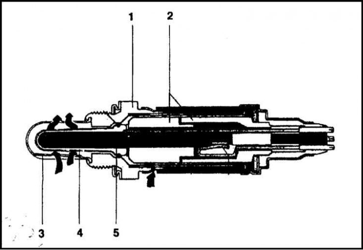
1 - Housing; 2 - Ceramic tube; 3 - Protective cap; 4 - Active zone; 5 - Contacts
The λ-probe is installed in the exhaust pipe of the exhaust system. The operating temperature of the sensor exceeds the value of 300°C, when in the active zone of the device there is a change in the resistance of the working element, depending on the level of oxygen in the exhaust gases. If the amplitude of the signal generated by the sensor is outside the allowable range corresponding to the optimal ratio of the components of the air-fuel mixture, the ECU issues a command to adjust the amount of fuel injected and the ignition timing, thereby maintaining optimal conditions for the most complete combustion of the mixture and reducing the level of toxic components in the exhaust gases. In case of failure of the λ-probe, the system switches to the emergency operation mode, accompanied by a decrease in dynamic performance and an increase in fuel consumption. The corresponding fault code is stored in the memory of the control unit.
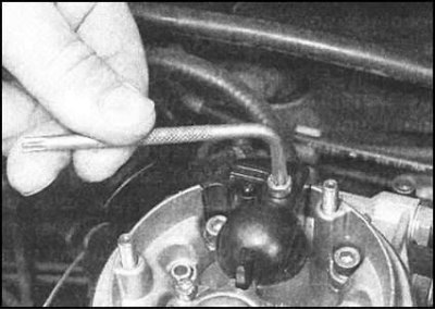
Coolant temperature sensor
1. The temperature sensor of the fuel injection system is installed at the rear of the intake manifold. In addition to it, a separate sensor is provided that ensures the operation of the temperature meter - CTS (see chapter Cooling, heating systems). In the event of a malfunction of the sensor, the system switches to emergency operation, while there may be a violation of the stability of the cold engine speed.
2. The sensor can be checked by measuring its electrical resistance, which should be about 2 kOhm when the engine is cold, and about 300 Ohm when it is hot.
3. If a break is detected, the sensor must be replaced. If the resistance changes with temperature, you should drive the car to a service station for a more detailed check of the engine management system - the sensor failure code in some cases is recorded in the system's ECU memory in the form of a corresponding code that can be determined using a special diagnostic reader.
4. To remove the sensor, you must either completely empty the cooling system, or disconnect one of the hoses of the cooling path from the pipeline and empty the latter. Alternatively, prepare a suitable plug to block the sensor's mounting hole after the sensor has been unscrewed.
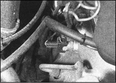
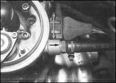
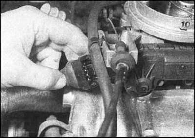
5. Disconnect the electrical connector, then unscrew the sensor from the back of the pipeline (see accompanying illustration). Remove the seal - during assembly it must be replaced without fail.
6. Install a new seal and screw the sensor into place.
7. Connect the electrical wiring and, as necessary, top up the cooling system.
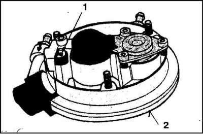
RPM and crankshaft position sensor
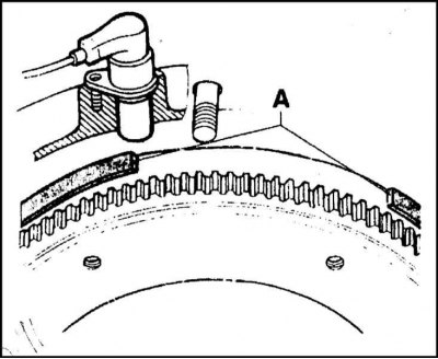
The crankshaft speed and position sensor is mounted on the clutch dome and is an induction assembly that informs the ECU about the speed and position of the equipped with an induction ring (A) flywheel. The induction ring has cutouts spaced at 54°. The sensor is installed so as to generate an information pulse at points 60°and 6°before TDC. Analyzing the information coming from the sensor, the ECU determines the moment of fuel injection, and if the maximum allowable crankshaft speed is exceeded (5800 rpm) or shuts off the fuel supply during engine braking. When replacing the sensor, ensure that it is correctly positioned on the clutch dome. Procedures for removing and installing the sensor are described in Chapter Engine electrical equipment.
Electronic control unit (ECU)
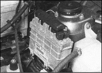
The ECU is located at the rear on the left bulkhead of the engine compartment). The block is protected by a special code and should not be removed without prior consultation with representatives of the Skoda branded service center. Unauthorized disconnection of the multi-pin connector may result in malfunction of the ECU.
Fuel pump relay and fuses
1. The fuel pump relay and injection system fuses are located in the mounting block installed in the vehicle interior (see chapter Onboard electrical equipment).
2. The pump relay is in the fifth position in the relay row of the operating panel of the mounting block. The electrical circuit of the pump power circuit is protected by fuse No. 4.
3. The relay is removed from its socket by simple pulling. The installation of the relay is unambiguous due to the asymmetry of the shape of the socket.
4. The fuse is removed in the same way as all other fuses (see chapter Onboard electrical equipment).
5. It should be noted that the removal of the main fuse of the injection system (№ 1) causes the adaptation data to be erased from the ECU memory, just like when the battery is disconnected. Reloading the operating parameters takes some time, which can lead to a violation of the stability of the idle speed during the first few minutes after the first start of the engine.