
Components of the front section of the exhaust system
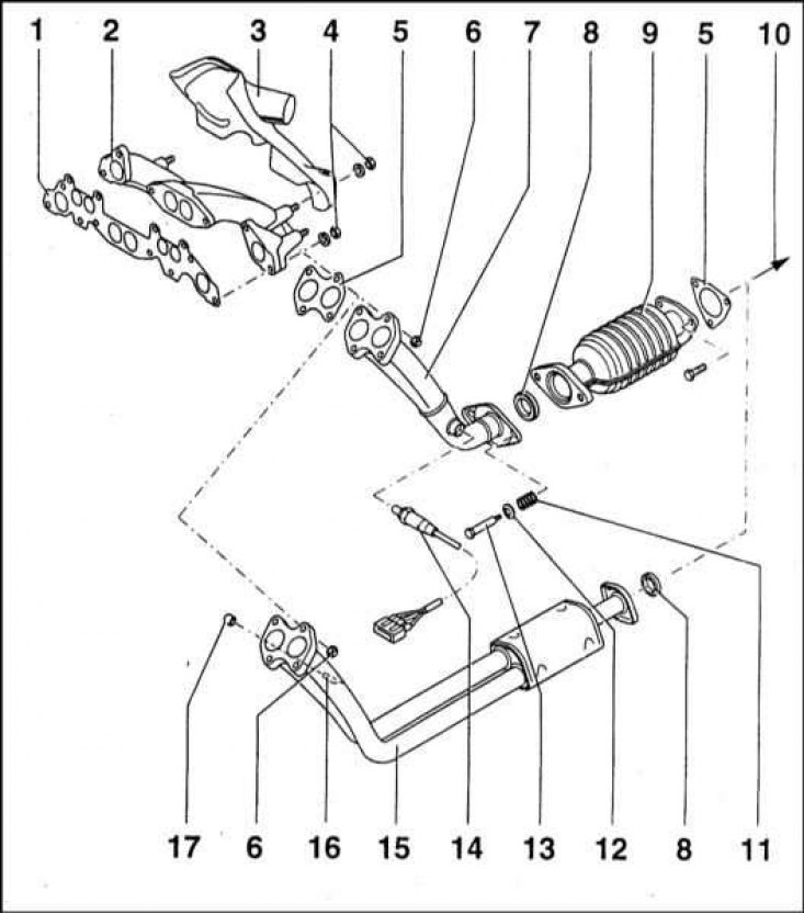
1 - Sealing gasket; 2 - Exhaust manifold; 3 - Casing of the intake air heater; 4 - Nut; 5 - Sealing gasket; 6 - Nut; 7 - Downpipe (fuel injected models); 8 - O-ring; 9 - Catalytic converter (fuel injected models); 10 - To the middle section of the exhaust system; 11 - Spring; 12 - Spring plate; 13 - Bolt; 14 - λ probe (fuel injected models); 15 - Downpipe (carburetor models); 16 - Gas analyzer for determining the level of CO; 17 - Cork
Components of the middle and rear sections of the exhaust system
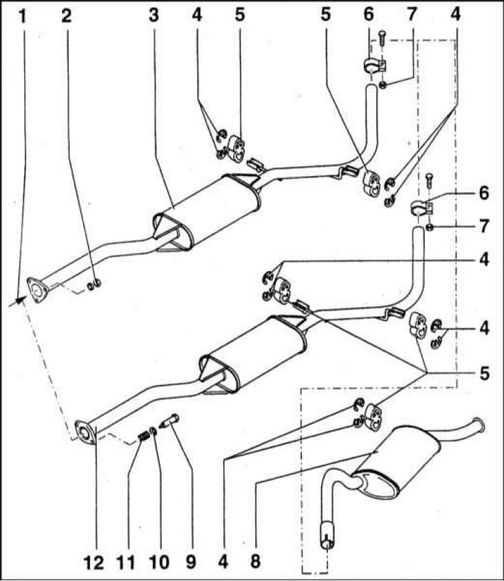
1 - Flange for fastening to the downpipe / catalytic converter; 2 - Fixing nut; 3 - Middle section with central muffler (fuel injected models); 4 - Lock washer; 5 - Rubber suspension; 6 - Clamp; 7 - Nut; 8 - Rear muffler; 9 - Bolt; 10 - Spring plate; 11 - Spring; 12 - Middle part with central muffler (carburetor models)
General information
The exhaust system of all models consists of a front pipe, a catalytic converter (if provided), center section with front muffler and exhaust section with rear muffler.
Note. On diesel models and petrol models 1.6 l, the catalytic converter can be mounted in the downpipe of the system, on models 1.3 l it is presented in a separate section. Carburetor models are not equipped with a catalytic converter. The illustrations show the designs of the exhaust systems used on the vehicles in question.
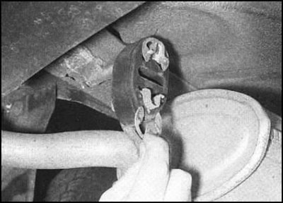
Sections of the system along its entire length are suspended from the bottom of the car by means of rubber loops clinging to metal brackets.
Removing
Attention! Start work only after the final cooling of the system. Particular attention should be paid to the condition of the catalytic converter, whose operating temperature is very high. To ensure complete safety, carry out all procedures with protective gloves.
1. Each section of the exhaust system is removed individually.
2. To remove any of the sections of the system, jack up the rear or front of the car, respectively. Alternatively, you can drive the vehicle overpass or park it over a viewing hole.
Downpipe (models 1.3 l)
1. Remove the λ-probe (see Section Removal and installation of λ-probe).
2. Support the catalytic converter. Loosen the two fixing bolts of the flange connecting the receiving pipe to the converter section. Remove washers and retainer springs. After dismembering the flange connection, remove the sealing ring - try to remember its installation direction (flat side forward).
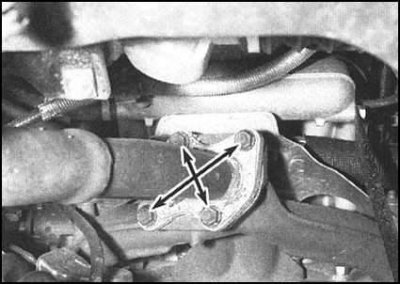
3. Supporting the intake section, in several stages, give four nuts securing it to the exhaust manifold. Lower the section and remove it from under the vehicle.
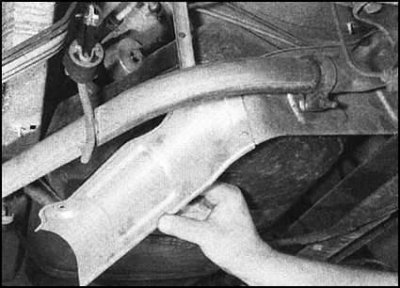
Catalytic converter (models 1.3 l)
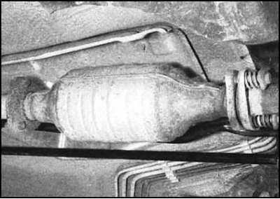
1. Support the catalytic converter. Loosen the three nuts of the section rear flange connection, remove the bolts, and remove the washers.
2. Turn out two bolts of forward flange connection, remove washers and locking springs. After dismembering the connection, remove the sealing ring. When assembling, the ring should be installed with the flat side facing forward. Gently lower the transducer assembly to the ground (see Section Catalytic converter - general information and precautions) and remove it from under the car.
Downpipe assembly with catalytic converter (diesel models and petrol models 1.6 l)
1. Support the front muffler or intake section assembly with wooden blocks. On 1.6L petrol models, remove the λ-probe (see Section Removal and installation of λ-probe).
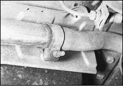
2. Give a nut of a coupling bolt of a collar of fastening of a reception pipe to the central section of system of release. On 1.6L models, remove washer and spacer.
3. Give fixing nuts and separate receiving section from a final collector. Remove the seal. Separate the downpipe from the central section of the system (see Section Catalytic converter - general information and precautions). And take it out from under the car.
Assembling the center section with the front muffler
1. Support the catalytic converter, then loosen the clamp bolt or flange bolts and separate the front of the center section from the catalytic converter. On 1.3L models, remove the gasket.
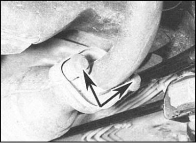
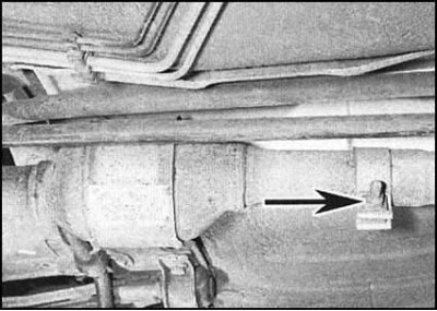
2. Loosen the tie bolt of the clamp that secures the rear of the center section to the exhaust pipe. Remove the suspension loops from the support brackets and remove the central section of the system from under the vehicle. The rubber loops of the suspensions are attached to the brackets using two large clamps, which must first be removed.
Assembling the exhaust section with the rear muffler
1. Loosen the tie bolt of the clamp that secures the outlet to the center section. Disconnect the sections.
2. Remove the clips, remove the exhaust section from the support brackets and remove it from under the vehicle.
Thermal shield (s)
Heat shields are attached to the underbody panels of the vehicle with nuts, bolts and clamps. Each of the screens can be removed after dismantling the corresponding section of the exhaust system. If the screen is being removed to gain access to the components underneath, sometimes it is enough to just loosen the fasteners and tilt the screen shield slightly, without dismantling the exhaust system sections.
Installation
Installation is in the reverse order. Particular attention should be paid to the following points:
- a) Before docking the system sections, carefully clean the mating surfaces from corrosion. Coupling bolts and nuts of clamp connections will be correctly replaced;
- b) Do not forget to check the condition of the rubber loops of the support hangers of the system sections. Defective hinges must be replaced;
- c) The mating surfaces of the clamp connections should be lubricated with a special sealing paste;
- d) Before final tightening of the fasteners, make sure that the rubber loops of the hangers are properly seated. Remember that the system must not come into contact with the vehicle's suspension and body components;
- e) Tighten fasteners with the required force evenly in several steps.