



EGR Valve Installation Components
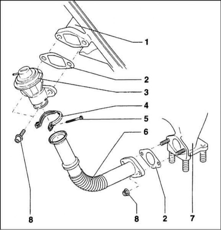
1 - Inlet manifold; 2 - Gasket; 3 - EGR valve; 4 - Fastening clamp; 5 - Tightening screw; 6 - Connecting tube; 7 - Exhaust manifold; 8 - Fastening nut
General information
The system consists of an EGR actuator valve, an EGR control solenoid valve, a diesel control unit and connecting vacuum hoses.
The EGR valve is secured to the intake manifold using a flange connection. The second flange of the valve is connected to the exhaust manifold using a semi-rigid tube.
The EGR solenoid valve/modulator is mounted to the rear of the engine compartment via a bracket.
The EGR system is controlled by the diesel control unit, also located in the rear of the engine compartment, next to the glow plug relay. The control unit activates the EGR system only in the engine speed range from 825 rpm to 3200 rpm. Outside the specified range, the system is disabled.
The EGR system is also designed to be switched off during the first two seconds from the start of acceleration, as well as when the vehicle is moving at an altitude of over 1000 m above sea level.
Replacement of components
EGR valve
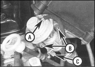
1. Disconnect the vacuum hose from the fitting on the top of the EGR valve.
2. Remove the bolts securing the valve to the intake manifold flange. Remove and discard the sealing gasket.
3. Unscrew the clamping screw of the fastening clamp and disconnect the valve from the semi-rigid tube coming from the exhaust manifold. If necessary, loosen the fastening nuts and remove the semi-rigid tube from the exhaust manifold (don't forget to remove the sealing gasket as well).
4. Installation is carried out in reverse order. Please note the following points:
- a) Do not forget to replace the flange joint sealing gasket;
- b) If the semi-rigid tube has been removed, also replace its sealing washer. Loosely screw in the mounting bolts and make sure that the tube is not twisted or under load before tightening them to the required torque.
EGR electromagnetic valve modulator
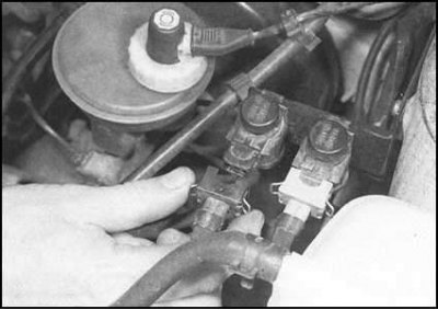
1. Make sure the ignition is off, then disconnect the electrical wiring from the valve. Do not confuse the valve connector with the gray colored idle speed increase device connector located nearby.
2. Loosen the clamps and disconnect the hoses from the valve fittings. Try to remember the orientation of the valve in the tract.
3. Installation is carried out in reverse order.
Attention! Make sure the vacuum hoses are connected correctly. Failure of the EGR system will reduce the efficiency of the combustion process of the air-fuel mixture and increase the smoke content of the exhaust.