



2. Lubricate the crankshaft journals with engine oil and place the shaft on the bearing beds.
3. Insert the liners without grooves into the main bearing caps and lubricate them with engine oil.
4. For all engines except the 1.0L engine, lubricate the thrust washers with engine oil and insert them into the center main bearing cap (grooves to the crankshaft cheeks).
5. Install the main bearing caps according to the marks on them (the bearing numbers are stamped on the side of the covers). The first bearing is considered to be on the camshaft drive side.
Information published on the website: SKODABOOK
6. Tighten the main bearing cap bolts for the 1.0L, 37 kW and 1.4L, 50 kW engines to 75 Nm, for the 1.9L, 74 kW diesel engine – 65 Nm, then tighten another 90°. First, tighten the bolts of the middle cover (third), then the adjacent ones (second and fourth) and last but not least the extreme ones (first and fifth). Turn the crankshaft, it should rotate easily, without jamming.
7. Install the rear oil seal retainer. For 1.0 l, 37 kW and 1.4 l, 50 kW engines, first lubricate the seal lip with engine oil and apply Loctite 574 sealant to the holder and the threads of the holder mounting bolts. Tighten the bolts to a torque of 8 N·m.
8. Install the flywheel, keeping in mind that on all engines except the 1.0L 37kW and 1.4L 50kW engines, it can only be installed in one position due to the asymmetrical arrangement of the holes. Replace the flywheel mounting bolts with new ones and tighten them to a torque of 60 Nm, then turn them an additional 90°.
9. For 1.0 l, 37 kW and 1.4 l, 50 kW engines, lubricate the camshaft journals and cams with engine oil and install the shaft into the cylinder block. Install the locking plate 9 (see figureCamshaft of 1.0 l, 37 kW and 1.4 l, 50 kW engines) and tighten the bolts 10 of its fastening to a torque of 5 Nm.
10. For 1.0L 37kW and 1.4L 50kW engines, install the cylinder liners so that they do not touch each other. Check the protrusion of the sleeves (see subsection 2.13.2).
11.Place the piston on the connecting rod so that the arrow on the piston bottom and protrusion B (see figureParts of the connecting rod and piston group of the 1.4 liter, 55 and 74 kW engine and drawing Connecting rod and piston group parts of a 1.9 l, 74 kW diesel engine) on the lower head of the connecting rod were directed in one direction. For 1.0 l, 37 kW and 1.4 l, 50 kW engines, the arrow points towards the camshaft and is located on the side of hole B (see figure Connecting rod and piston group parts for 1.0 l, 37 kW and 1.4 l, 50 kW engines) in the connecting rod for lubricating the piston pin. Additionally, the pistons must be of the same weight group (the "+" or "-" group designation is stamped on the piston crown). Lubricate the piston pin with engine oil and insert it into the piston and connecting rod. Install the piston pin retaining rings into the grooves on the piston. If the finger fits too tightly into the piston holes, heat the piston to 60°C.
12. Install the rings on the pistons. The best way to do this is with a piston ring puller. In gasoline engines, the oil scraper ring is composite, so it must be installed manually, carefully separating the ring joints. The rings are installed with the inscription TOP facing upwards, towards the bottom of the piston. The rings must rotate freely in the piston grooves, and their locks must be located at an angle of 120° to each other.
13. Insert the bearing shells into the connecting rod small ends and connecting rod caps. Diesel engines have a black stripe on the upper bearings on the working surface near the edge. For 1.4 L, 50 kW engines, the retaining tabs of the liners must fit into the grooves of the connecting rod and cover; for other engines, the liners must be installed so that the connecting rod head and cover protrude the same distance in width on both sides of the liners. Lubricate the bearings with engine oil.
14. Compress the piston rings with a mandrel and carefully insert the connecting rod with the piston into the cylinder, while the arrow on the bottom of the piston should be directed towards the camshaft drive (for 1.0 l, 37 kW and 1.4 l, 50 kW engines the arrow points towards the camshaft). The ring compression mandrel must be pressed against the cylinder block. By striking the bottom of the piston with the hammer handle, move it from the mandrel into the cylinder.
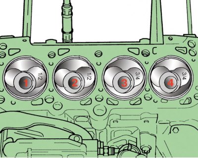
15. In a 1.9 liter, 74 kW diesel engine, pistons are installed in the first and second cylinders with a recess for the inlet valve (larger size), directed towards the rear of the engine (flywheel), and towards the front of the third and fourth cylinders (camshaft drive), as shown in the figure.
16. Install the connecting rod cap with the liner onto the connecting rod, ensuring that the cylinder numbers stamped on the cap and the connecting rod are on the same side.
17. Tighten the connecting rod bolts; for a 1.4L, 50 kW engine, tighten the connecting rod bolt nuts. For all engines except the 1.4L 50kW, replace the connecting rod bolts with new ones, lubricating the threads and the surface of the head that comes into contact with the cover with engine oil before tightening them. Tighten the bolts (for the 1.4L 50 kW engine - the connecting rod nuts) on the 1.0L 37 kW and 1.4L 55 and 74 kW engines to 20 Nm, then tighten a further 90°; on 1.4 l, 50 kW engines – 40 Nm; on 1.9 l, 74 kW diesel engines – 30 Nm, then turn another 90°.
18. For 1.0L 37kW and 1.4L 50kW engines, install the timing gears (see subsection 2.5) and the timing gear cover.
19. Install the oil pump (see subsection 3.3).
20. Apply sealant to the oil pan flange, install the pan and tighten the mounting bolts.
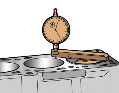
21. For a diesel engine, select a cylinder head gasket according to thickness. To do this, measure the protrusion of the pistons at TDC above the upper plane of the block, as shown in the figure. Depending on the amount of piston protrusion, select a new gasket, taking into account the largest amount of protrusion.
22. Spare parts are supplied with gaskets of various thicknesses, which are marked with the number of holes 3 (see figure Diesel engine cylinder head gasket markings). A gasket with a thickness of 0.91–1.0 mm has one hole, a gasket with a thickness of 1.01–1.10 mm has two holes, and a gasket with a thickness of 1.11–1.20 mm has three holes.
23. Install the cylinder head (see subsection 2.7) and engine attachments.