
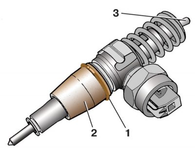
Injector pump with fasteners
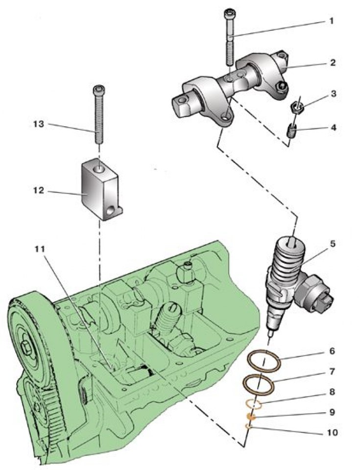
1 – a bolt of fastening of an axis of yokes; 2 - the axis of the rocker arms; 3 - locknut; 4 - adjusting screw; 5 - pump-injector; 6 - top sealing ring; 7 – an average sealing ring; 8 - lower sealing ring; 9 - heat-insulating ring; 10 - retaining ring; 11 – a head of the block of cylinders; 12 – pump-injector holder; 13 - holder fastening bolt
Installing pump injectors
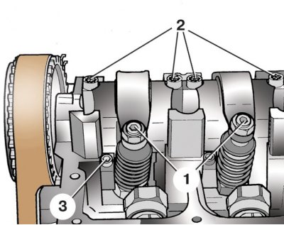
1 - adjusting screws; 2 – bolts of fastening of an axis of yokes; 3 – a bolt of fastening of the holder of a nozzle
1. Remove the camshaft drive belt top cover.
2. Remove the block head cover.
3. Turn the crankshaft so that the rocker arms do not press on the pusher of the injector to be replaced.
4. Loosen the locknuts 3 and unscrew the adjusting screws 4 so that the rocker arms touch the spring plates of the unit injectors.
5. Remove bolts 2 (see fig. Installing pump injectors) fastening the axis of the rocker arms, while first unscrewing the two extreme bolts, then the two middle ones.
6. Remove an axis with yokes in gathering.
7. Turn away a bolt 3 fastenings and remove the holder of the pump-injector.
8. Using a screwdriver, disconnect the block with wires from the injector.
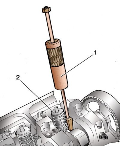
9. Inserting a special puller into the groove of the unit injector under the holder, as shown in the figure, remove the unit injector 2 (1 - puller Т10055). Mark the pump injectors so as not to confuse them during installation.
10. Inspect o-rings 6, 7 and 8 (see fig. Injector pump with fasteners), replace cracked, torn or loose rings.
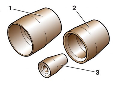
11. To install new rings, the manufacturer recommends using a set of mandrels T10056 (1 - mandrel for the upper ring; 2 - mandrel for the middle ring; 3 - mandrel for the lower ring).
12. Carefully, so as not to damage the seats on the nozzle, remove the old o-rings.
13. Remove retainer 10 (see fig. Injector pump with fasteners) and heat-insulating 9 rings so that they do not interfere with the installation of mandrels.
14. Thoroughly wipe the seats under the O-rings on the nozzle.
15. Put on the nozzle mandrel 2 for the upper sealing ring and move the sealing ring 1 along it onto the nozzle without twisting it (3 - nozzle pusher).
16. Install the middle and bottom O-rings in the same way. Install the heat seal and circlip.
17. Inspect the adjusting screw and pusher 3 nozzles: if at least one of them shows signs of wear, replace the screw and pusher.
18. Lubricate the lower end of the adjusting screw and the spherical surface of the nozzle pusher with grease.
19. Lubricate the nozzle sealing rings with a thin layer of engine oil, carefully insert the nozzle into the head of the block and, gently pressing it, insert it into the head until it stops.
20. Install the nozzle holder so that its protrusion fits into the groove of the nozzle. The holder bolt needs to be replaced. Screw in a new bolt without tightening it completely.
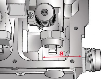
21. It is very important that the holder and nozzle are installed perpendicular to the plane of the head of the block, otherwise the holder fastening bolt may turn away, which will lead to failure of the unit injector. In order for the unit injectors to be installed strictly vertically, it is necessary to maintain the distance a between the rear outer plane of the block head and the surface of the unit injector: the fourth cylinder is 64.8±0.8 mm, the third cylinder is 152.8±0.8 mm, the second cylinder is 244.2±0.8 mm, the first cylinder 332.2±0.8 mm.
22. After adjusting the distance a, tighten the holder fastening bolt to 12 Nm, then tighten it another 270° (3/4 turn).
23. Install the rocker axle. The axle bolts need to be replaced. Screw in by hand first the two inner axle mounting bolts, then the two outer ones. After that, tighten the inner bolts to a torque of 20 Nm, tighten the two outer bolts with the same torque. Tighten the inner bolts, and then another 90°extreme.
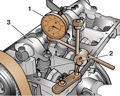
24. Turn the crankshaft so that rocker 3 sinks the injector pusher as far as possible, this can be checked using indicator 1 (2 - pump nozzle).
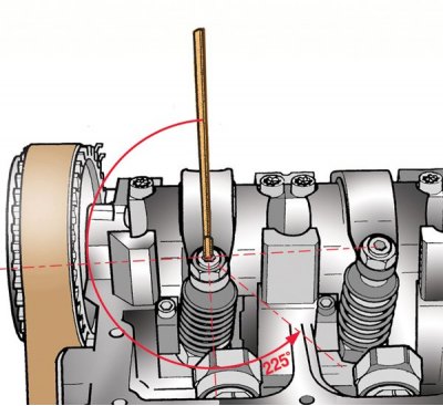
25. Screw the adjusting screw into the injector pusher until you feel it, then another 225°, and then turn it back a little, as shown in the figure.
26. While holding the adjusting screw in this position, tighten its locknut to 30 Nm.
27. Install all removed parts in reverse order.
Tightening torques, Nm
| Lambda probe | 50 |
| Bolt of fastening of an inlet branch pipe | 8 |
| Screw for fastening the fuel rail of the engine 1.4 l, 55 and 74 kW | 10 |
| Bolt of fastening of the case of the thermostat | 10 |
| Bolt of fastening of an axis of rocker arms of the engine of 1,9 l, 74 kW | 20 and tighten by 90° |
| Bolt of fastening of the holder of a nozzle of the engine 1,9 l, 74 kW | 12 and tighten by 270° |
| Fuel pipe union nut | 25 |
| Fuel Conductor Bolt | 10 |