Contents: Removal ⬇ Installation ⬇
Removal
Note: All removed thermal insulation coating elements must be returned to their original position during installation.
Please note: If mechanical damage to the turbocharger is detected, it may not be the only component that needs to be replaced. Turbocharger damage can be caused by problems with the intake system. In case of mechanical damage, the turbocharger must be checked:
- Check the air filter housing, filter element and air duct pipes for contamination.
- Check the charge air ducts and intercooler for foreign particles.
- If blockages and foreign particles are detected, it is necessary to flush and dry all the intake system pipes and replace the intake system filter element, if necessary.
1. Drain the coolant into a pre-prepared container (for more details, see the relevant section in the chapter "Cooling system").
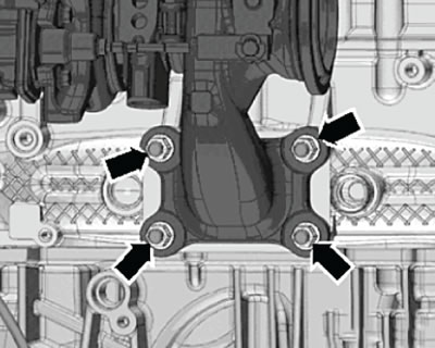
2. Unscrew the mounting bolts and remove the thermal insulation coating of the inner constant velocity joint of the right drive shaft.
3. Remove the thermal insulation coating.
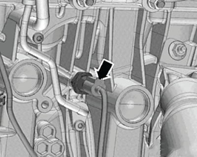
4. Disconnect the wiring harness connector (arrow) from the engine oil pressure sensor of the pressure relief line, as shown in the figure below.
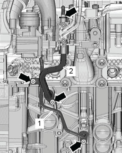
5. Unscrew the mounting screws (arrows), then disconnect and remove the pressure oil line tube (1) and the drain oil line tube (2), as shown in the figure below.
6. Unscrew the fastening screw (2) and remove the mounting clamp, as shown in the figure below.
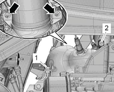
7. Unscrew the mounting screw (1) and loosen the mounting nuts (arrows) shown in the figure below, then hang up the catalytic converter assembly.
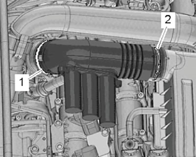
8. Loosen the mounting clamps (1) and (2), then disconnect the air duct pipes of the intake system, as shown in the figure below.
9. Release the air hoses from the clamps on the air duct pipe.
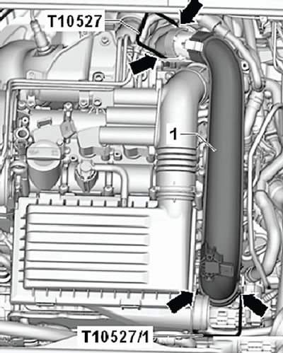
10. Unlock the clamps (arrows) using the special tool (T10527) and remove the air duct pipe assembly, as shown in the figure below.
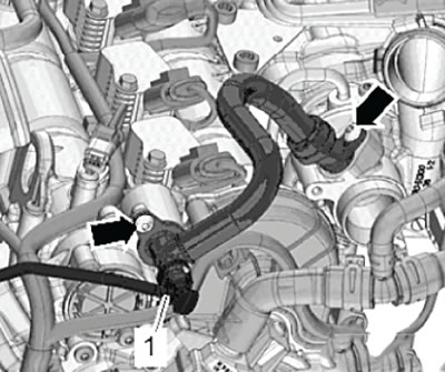
11. Press the release buttons and disconnect the hose (1) for the activated carbon filter, as shown in the figure below.
12. Unscrew the fastening screws (arrows) and disconnect the crankcase ventilation hose shown in the figure below.
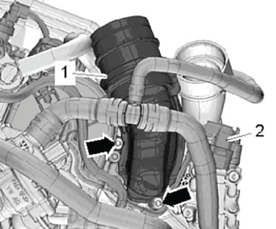
13. Disconnect the wiring harness connector (2) shown in the figure below.
14. Unscrew the fastening screws (arrows) and remove the connecting tube (1), as shown in the figure below.
15. Loosen the fastening clamp (3) shown in the figure below, then disconnect the water hose.
16. Unscrew the mounting screws (arrows) and, after disconnecting them from the cylinder head, move the pipes (1) to the side, as shown in the figure below.
Note: Using special tools (2), clamp the pipes as shown in the figure below.
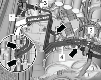
17. Loosen the mounting screws (arrows) and remove the support together with the thermal insulation coating (1), as shown in the figure below.
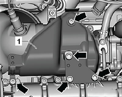
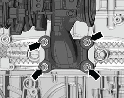
18. Loosen the mounting nuts (arrows) and remove the turbocharger assembly, as shown in the figure below.
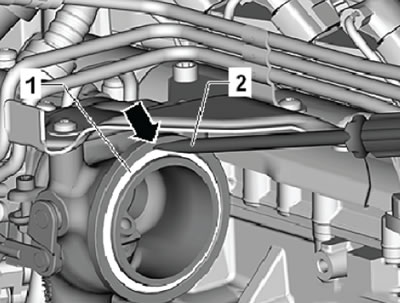
19. Insert a flat-head screwdriver (2) into the recess (arrow) of the turbocharger housing and, using a lever motion, remove the sealing ring (1), as shown in the figure below.
Installation
Installation is carried out in the reverse order of removal.
Note:
- After disassembly, it is always necessary to replace gaskets, sealing rings and nuts securing the cylinder head.
- Before connecting the pipes, fill the turbocharger with fresh engine oil.
- Sequence and tightening torques of the turbocharger assembly mounting nuts
- The fastening nuts are tightened in several steps, crosswise.
| Approach | Nuts | Tightening torque |
| 1 | 1...4 | 7 Nm |
| 2 | 1...4 | 10 Nm |
| 3 | 1...4 | 10 Nm |
| 4 | 1...4 | 14 Nm |