Vehicles with petrol engines
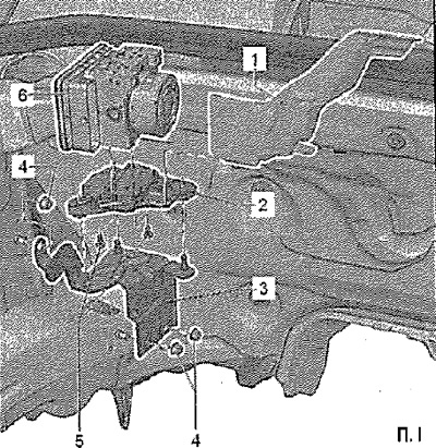
Installation location: The control unit is connected to the hydraulic unit by means of threaded connections and is located in the engine compartment on the right side.
Attention! Do not bend the brake lines at the hydraulic unit.
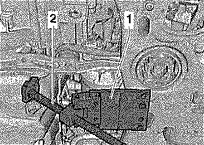
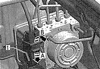
Read and write down the existing ECU code, Disconnect the battery. Remove engine cover. Remove protective cover -1- (if it exists).
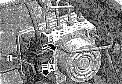
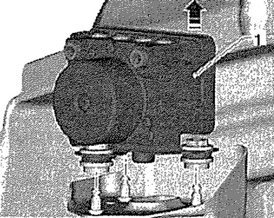
Unlock connector -1- -in direction of arrow A- and disconnect from control unit in -direction of arrow B-. Fit brake pedal depressor, eg -VAG 1869/2-. Attach the suction air bleed hose to the front left brake caliper bleeder and open the bleeder. Depress the brake pedal by at least 60 mm using a brake pedal depressor, eg -VAG 1869/2-. Seal front and rear left bleeder plugs. Do not remove brake pedal eg -VAG 1869/2-. Put a sufficient amount of lint-free rags under the computer and around the hydraulic unit.
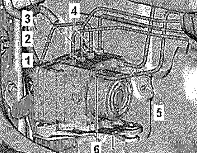
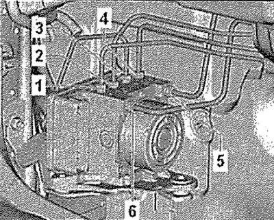
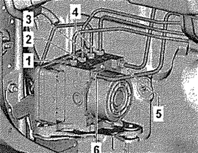
Make sure that brake fluid does not get on the contacts. Mark both brake lines -5- and -6- from brake master cylinder and unscrew from hydraulic unit. Seal off brake lines and tapped holes immediately using plugs from repair kit -1HO 698 311 A-. Mark the brake pipes (brake caliper) -1- to -4-, unscrew and plug. Remove the hydraulic unit with the computer from the dampers.
Attention! The ABS control unit -J104- and the ABS hydraulic unit -N55- must not be separated. Hydraulic pump and ABS hydraulic unit -N55- must not be separated.
Installation
Note: The plugs on a new hydraulic unit may only be removed when the appropriate brake line has been installed. If the plugs are removed from the hydraulic unit prematurely, the brake fluid may leak out, resulting in insufficient filling and air in the unit. Pay attention not to squeeze out the rubber support when mounting the holder from the console. After installation, check that the ABS computer is securely fastened, otherwise it may malfunction.
Installation in reverse order. Observe the tightening sequence of the threaded connections of the brake pipes.
Brake pipe tightening sequence
Remove brake depressor, eg -VAG 1869/2-. Remove air from the brake system. Code control unit -J104-. The basic setting of the steering angle sender -G85-, the lateral acceleration sender -G200-, the brake pressure sender 1 -G201- and the longitudinal acceleration sender -G251- must be carried out.
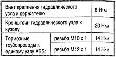
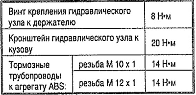
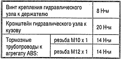
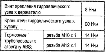
Tightening torques
Vehicles with diesel engines without particulate filter
Installation location: The control unit is connected to the hydraulic unit by means of threaded connections and is located in the engine compartment on the right side.
Attention! Do not bend the brake lines at the hydraulic unit!
Read and write the existing ECU code. Disconnect battery. Remove engine cover. Remove protective cover -1- (if it exists). Unlock connector -1- -in direction of arrow A- and disconnect from control unit in -direction of arrow B-. Install brake depressor, eg -VAG 1869/2-, Fit suction bleed hose onto front left brake caliper bleeder and open bleeder. Depress the brake pedal by at least 60 mm using the brake pedal depressor, eg -VAG 1869/2-. Plug the front and rear left bleeder plugs. Do not remove brake pedal eg -VAG 1869/2-. Put a sufficient amount of lint-free rags under the computer and around the hydraulic unit. Make sure that brake fluid does not get on the contacts. Mark both brake pipes -5- and -6- from brake master cylinder and unscrew from hydraulic unit. Seal off brake pipes and tapped holes immediately using plugs from repair kit -1H0 698 311 A-. Mark the brake lines (brake caliper) -1- to -4-, unscrew and plug. Remove the hydraulic unit with the computer from the dampers.
Attention! The ABS control unit -J104- and the ABS hydraulic unit-N55- must not be separated. Hydraulic pump and ABS hydraulic unit -N55- must not be separated.
Installation
Note: The plugs on a new hydraulic unit may only be removed when the appropriate brake line has been installed. If the plugs are removed from the hydraulic assembly prematurely, brake fluid may leak out, resulting in insufficient filling and air in the assembly. Pay attention not to squeeze out the rubber support when mounting the holder from the console. After installation, check that the ABS computer is securely fastened, otherwise it may malfunction.
Installation in reverse order. Observe the tightening sequence of the threaded connections of the brake lines.
Brake pipe tightening sequence
Remove brake depressor, eg -VAG 1869/2-. Remove air from the brake system. Code control unit -J104-. For this, the basic setting of the steering angle sender -G85-, the lateral acceleration sender -G200-, the brake pressure sender 1 -G2OT- and the longitudinal acceleration sender -G251- must be carried out.
Tightening torques
Vehicles with diesel engines with particulate filter (vehicles with front wheel drive)
Installation location: The control unit is connected to the hydraulic unit by means of threaded connections and is located in the engine compartment on the right side.
Attention. Do not bend the brake lines at the hydraulic unit.
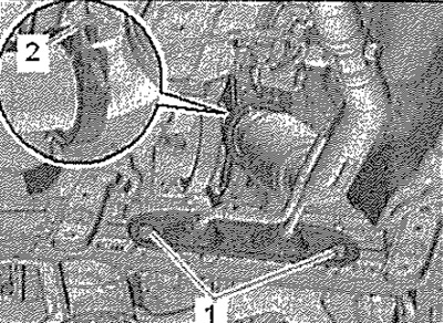
Read and write the existing ECU code. Disconnect battery, remove engine cover. Remove protective cover -1- (if it exists). Unlock connector -1- -in direction of arrow A- and disconnect from control unit in -direction of arrow B-. Fit brake pedal depressor, eg -VAG 1869/2-. Attach the suction air bleed hose to the front left brake caliper bleeder and open the bleeder. Depress the brake pedal by at least 60 mm using the brake pedal depressor, eg -VAG 1869/2-. Plug the front and rear left bleeder plugs. Do not remove brake pedal eg -VAG 1869/2-. Put a sufficient amount of lint-free rags under the computer and around the hydraulic unit. Make sure that brake fluid does not get on the contacts. Mark both brake pipes -5- and -6- from brake master cylinder and unscrew from hydraulic unit. Brake lines and tapped holes immediately closed with plugs from repair kit -1H0 698 311 A-. Mark the brake pipes (brake caliper) -1- to -4-, unscrew and plug. Remove soundproof cover. Unscrew bolts -1- for lower power unit support. Secure bellows for front exhaust pipe with transport tool -T10404-.
Remove clamp -2-.
Push engine forward approx. by 4 mm.
1. Mounting plate -T30012/1A-
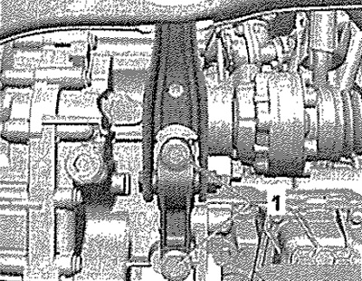
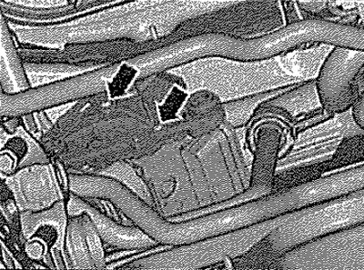
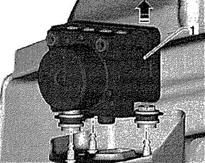
2. Engine stand -MRZ-470-. Detach control unit -1- in -direction of arrow- from damper.
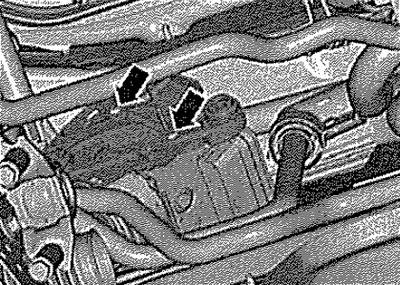
Remove bracket -arrows- in vehicle from hydraulic unit. Remove control unit with hydraulic unit from vehicle.
Attention! The ABS control unit -J104- and the ABS hydraulic unit -N55- must not be separated. Hydraulic pump and ABS hydraulic unit -N55- must not be separated.
Installation
Note: The plugs on a new hydraulic unit may only be removed when the appropriate brake line has been installed. If the plugs are removed from the hydraulic assembly prematurely, brake fluid may leak out, resulting in insufficient filling and air in the assembly. Pay attention not to squeeze out the rubber support when mounting the holder from the console. After installation, check that the ABS computer is securely fastened, otherwise it may malfunction.
Installation in reverse order. Observe the tightening sequence of the threaded connections of the brake pipes.
Brake pipe tightening sequence
Remove brake depressor, eg -VAG 1869/2-. Remove air from the brake system. Code control unit -J104-. For this, the basic setting of the steering angle sender -G85-, the lateral acceleration sender -G200-, the brake pressure sender 1 -G201- and the longitudinal acceleration sender -G251- must be carried out.
Tightening torques
Vehicles with diesel engines with particulate filter (vehicles with all-wheel drive)
Installation location: The control unit is connected to the hydraulic unit by means of threaded connections and is located in the engine compartment on the right side.
Attention! Do not bend the brake lines at the hydraulic unit.
Read and write the existing ECU code. Disconnect battery. Remove engine cover. Remove protective cover -1- (if it exists). Unlock connector -1- -in direction of arrow A- and disconnect from control unit in -direction of arrow B-. Fit brake pedal depressor, eg -VAG 1869/2-. Attach the suction air bleed hose to the front left brake caliper bleeder and open the bleeder. Depress the brake pedal by at least 60 mm using the brake pedal depressor, eg -VAG 1869/2-. Plug the front and rear left bleeder plugs. Do not remove brake pedal eg -VAG 1869/2-. Put a sufficient amount of lint-free rags under the computer and around the hydraulic unit.
Make sure that brake fluid does not get on the contacts. Mark both brake pipes -5- and -6- from brake master cylinder and unscrew from hydraulic unit. Seal off brake pipes and tapped holes immediately using plugs from repair kit -1H0 698 311 A-. Mark the brake pipes (brake caliper) from -1 - to -4-, unscrew and plug. Remove soundproof cover. Lower the front suspension to the service position.
Detach control unit -1- in -direction of arrow- from damper.
Remove bracket -arrows- in vehicle from hydraulic unit. Remove the control unit with hydraulic unit from the bottom of the vehicle.
Attention! The ABS control unit -J104- and the ABS hydraulic unit-N55- must not be separated. Hydraulic pump and ABS hydraulic unit -N55- must not be separated.
Installation
Note: The plugs on a new hydraulic unit may only be removed when the appropriate brake line has been installed. If the plugs are removed from the hydraulic assembly prematurely, brake fluid may leak out, resulting in insufficient filling and air in the assembly. Pay attention not to squeeze out the rubber support when mounting the holder from the console. After installation, check that the ABS computer is securely fastened, otherwise it may malfunction.
Installation in reverse order. Observe the tightening sequence of the threaded connections of the brake lines.
Brake pipe tightening sequence
Remove brake depressor, eg -VAG 1869/2-. Remove air from the brake system. Code control unit -J104-. For this, the basic setting of the steering angle sender -G85-, the lateral acceleration sender -G200-, the brake pressure sender 1 -G201- and the longitudinal acceleration sender -G251- must be carried out.
Tightening torques