



Contents: Removal ⬇ Petrol models ⬇ Diesel models ⬇ All models ⬇ Gearbox compartment ⬇ Installation ⬇
Removal
Note. The engine can only be removed from the vehicle together with the transmission. Disassembling the power unit for the purpose of carrying out a major overhaul of the engine can be done later on a workbench or assembly stand. The assembly of the unit is lowered from the engine compartment down and then removed from under the vehicle. Make sure that there is sufficient free space under the vehicle and that the latter is securely fixed in the raised position (see section Removal the power unit from the vehicle - preparation and precautions, general information about the power unit suspension).
1. Park the vehicle on a level, horizontal area with a hard surface, leaving enough free space around it. Remove the hood (see Chapter The procedure for assembling the engine after a major overhaul).
2. If the engine is to be disassembled, drain the engine oil and remove the oil filter. Clean, replace and tighten the oil pan drain plug securely.
3. Support the rear wheels with chocks and firmly apply the parking brake. Jack up the front of the vehicle, raising it to a height sufficient for dismantling the power unit. Securely fix the raised vehicle on strong supports. Remove both front wheels.
4. Drain the transmission oil, then clean thoroughly, screw back in place and tighten the drain plug.
5. Drain the cooling system.
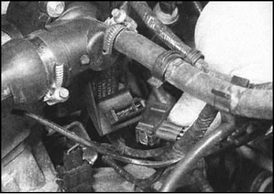
6. Unbolt the exhaust pipe and disconnect it from the exhaust manifold flange. On petrol models, follow the wiring from the L-probe to the connector and disconnect the sensor. Release the connector from the support bracket.
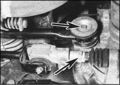
7. In accordance with the instructions given in Chapter Transmission, disconnect the gear selection rod and the shift mechanism rod from the manual transmission.
8. Remove the air cleaner (or just the air intake sleeve) - see the relevant Part of the Chapter Power supply system. On 1.3L and 1.6L petrol models equipped with Multiport Fuel Injection (MPFI), remove the throttle body cover.
9. Disconnect the battery and remove the generator.
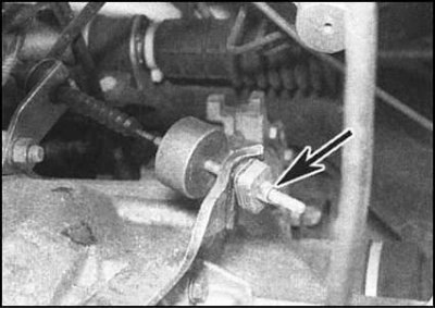
10. Turn the clutch actuator adjusting nut counterclockwise to loosen the cable as much as possible. Release the cable core from the clutch release lever and the sheath from its support bracket. Unbolt the cable support bracket and remove it together with the ground busbar (if the latter is provided).
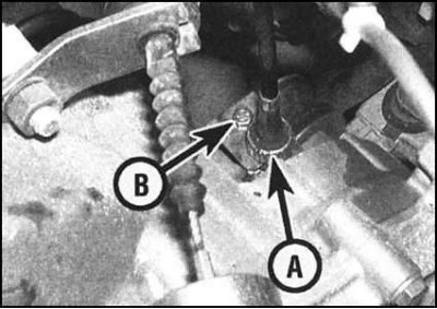
11. Loosen the side knurled retaining nut, then pull the speedometer drive cable up to disengage the drive from the rear of the gearbox. Alternatively, remove the retaining plate bolt and remove the drive pinion from the gearbox.
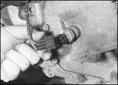
12. Disconnect the wiring from the reverse light switch sensor located underneath the front of the manual transmission housing. If equipped, release the switch sensor wiring from the retainer on the starter assembly.
13. Slide the rubber protective cover back from the main terminal of the starter solenoid relay, then loosen the nut and disconnect the wire coming from the battery from the terminal. Carefully disconnect the bayonet connector of the solenoid relay.
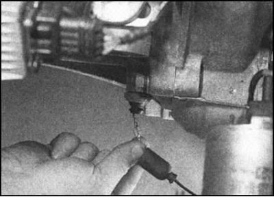
14. Disconnect the electrical wiring from the oil pressure switch. On petrol models, the sensor switch is located at the bottom of the front wall of the cylinder block (1.3 L models, or in the rear of the cylinder head (1.6 l models), on diesel models - on the left end of the head.
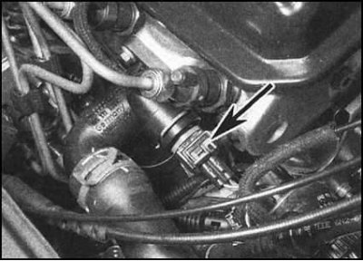
15. Disconnect the electrical wiring from the coolant temperature sensor (CTS) located on the thermostat housing or the elbow of the cooling tract (the sensor is installed on the branch pipe),...
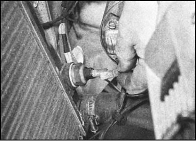
...and also from the sensor-switch...
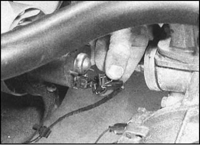
...and the electric motor of the cooling system fan.
16. On models with power steering or A/C, remove the accessory drive belt.
17. On models equipped with A/C, perform the following procedures:
- a) Disconnect the hose from the vacuum receiver;
- b) Disconnect the electrical wiring from the A/C compressor;
- c) Unbolt the compressor from the engine, move it to the side and tie it up securely. Try not to put any tension on the refrigeration line hoses.
18. On models with power steering, remove the steering pump (see Chapter Suspension and steering). It is not necessary to disconnect the hydraulic lines, it is enough just not to subject them to excessive loads when moving the pump. The pump should be installed in such a way that the lines cannot be damaged during the process of removing the power unit.
Petrol models
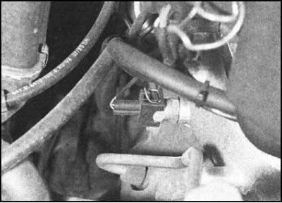
1. On 1.3 L models with central injection (SPFI), disconnect the following communication lines from the intake pipe/throttle body:
- a) Fuel supply and return hoses;
- b) Throttle body wiring (release the bandages, release the tourniquet from the intermediate fasteners and move it to the side);
- c) Throttle cable (gas cable);
- d) Brake booster hose;
- e) Cooling system hoses;
- f) Carbon adsorber purge hose;
- g) CTS wiring.
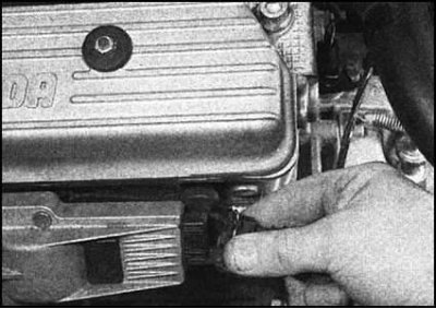
2. On the 1.3 L and 1.6 L models with distributed injection (MPFI), disconnect:
- a) Fuel supply and return hoses from the fuel pressure regulator;
- b) Vacuum hose from fuel pressure regulator;
- c) Electrical wiring of the power supply system (release the bandages, release the tourniquets from the intermediate fasteners and move them to the side);
- d) Wiring of the intake air temperature/pressure sensor;
- e) On 1.3L models - ignition coil unit wiring;
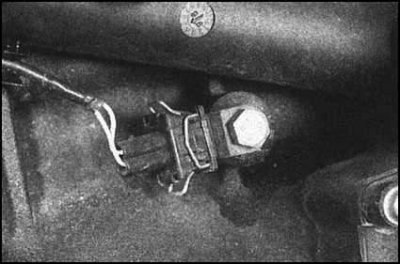
- f) Carbon adsorber purge hose;
- g) Brake booster hose from intake manifold;
- h) Wiring of the knock sensor on the rear of the engine block.
- i) On models equipped with A/C, unbolt the compressor and move it away from the engine, without disconnecting any refrigeration lines.
- j) Release the refrigeration line hoses/tubes from the intermediate clamps and also move them away from the engine.
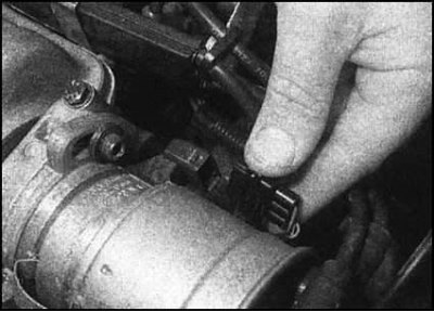
3. Disconnect the Hall sensor wiring. On 1.3L models, the 3-pin electrical connector is either mounted in a bracket attached to the thermostat housing or on top of the transmission housing. On 1.6L models, the sensor wiring connector is located on the ignition distributor.
4. If you have not done so already, disconnect the wiring from the ignition coil.
5. Remove the distributor cap, rotor and protective screen.
Diesel models
1. Disconnect the brake booster servo hose from the vacuum pump (see Chapter Brake system).
2. Disconnect the vacuum hose from the EGR valve (see Chapter Power supply system).
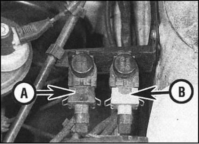
3. Perform the following procedures as necessary (see Part Diesel engine fuel system Chapters of the Power System):
- a) Loosen and unscrew the hollow bolts of the union connections, then disconnect the fuel supply and return hoses from the high-pressure fuel pump;
- b) Loosen the retaining clamp and disconnect the injector bleed hose from the port on the fuel return fitting;
- c) Loosen the clamps and remove the air intake hose from the intake manifold cover;
- d) Disconnect the gas cable from the fuel injection pump;
- e) Disconnect the wiring from the EGR and Idle Speed Control valves at the rear of the engine compartment. Try to remember the installation position of the connectors;
Information copied from the resource (SKODABOOK.ru)
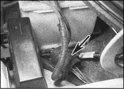
- f) Disconnect the multi-pin connector of the electrical harness located under the upper support of the left front suspension strut; The connector has a threaded fit and to disconnect it, you need to turn the casing. Having disassembled the connection, remove the inner seal. Note the presence of a red guide marking that determines the order of the connector mating. To prevent moisture and dirt from getting inside the connector, wrap both halves of it in polyethylene film;
- g) Disconnect the two electrical connectors mounted in the bracket on the left side of the engine. Also disconnect the ground wire located just above. Wrap the halves of the disconnected connectors in plastic film;
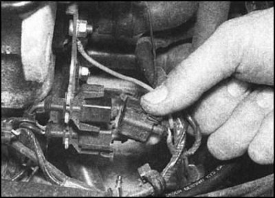
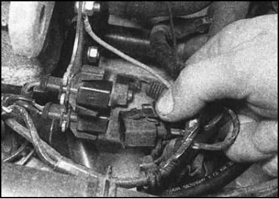
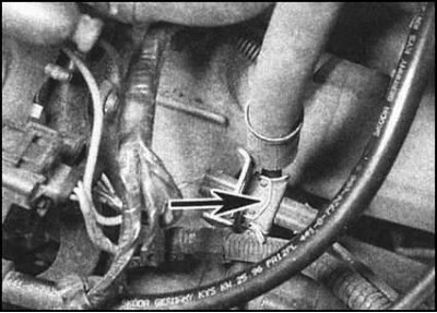
- h) Where required, disconnect the generator wiring harness connector.
All models
1. Following the instructions given in Chapters Engine electrical equipment and Power supply system, identify the sections of the engine, ignition and power supply electrical system wiring that remain connected to the sensors and actuators on the powertrain unit. Disconnect all remaining connectors that interfere with dismantling the powertrain, carefully marking them first to ensure correct mating during assembly.
2. Depending on the model, the powertrain may be equipped with one or more grounding straps. The straps are usually mounted either on the transmission housing, near the right support of the unit, or at the base of the engine oil dipstick guide tube. Disconnect all straps.
3. Remove the drive shafts from the transmission differential. To avoid damaging the CV joints, immediately tie the released ends of the shafts to the suspension elements with wire.
4. Hang the power unit using a winch or beam, completely removing its weight from the supports, but without disturbing the horizontal position. Since the unit is removed from the engine compartment through the lower opening, it would be unreasonable to prop it up from below.
5. To avoid damaging the oil pan, place an old floor mat, plywood, or just a sheet of cardboard under the engine compartment. After lowering, the unit must be moved forward, passing under the bumper for the purpose of final extraction from under the car, so having a trolley jack at hand will come in very handy.
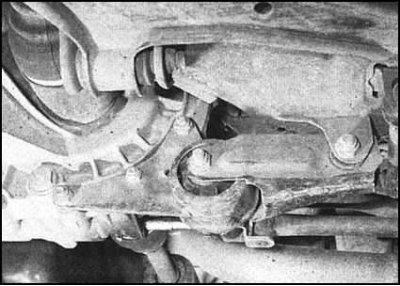
6. Remove the rear powertrain mount through bolt - see Part A or B of this Chapter.
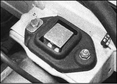
7. Mark the installation position of the left gearbox support. Loosen the self-locking nut, two bolts and remove the support plate from the top of the cushion.
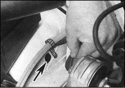
8. On 1.3L models, remove the rubber plug from the right mudguard,
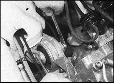
thus providing access to the through bolt of the right support. Loosen the nut and remove the bolt.
9. On diesel and 1.6L models, remove the two right-hand support bolts from below, directly above the crankshaft pulley. Remove the washers.
10. Make sure that no communications interfere with the removal of the power unit, enlist the help of an assistant and begin to carefully remove the assembly from the engine compartment, trying not to catch on surrounding components, such as the exhaust system receiving pipe or (with appropriate equipment) power steering system fittings. With the unit lowered to the floor/working platform of the trolley jack, carefully remove the assembly from under the vehicle.
11. Immediately transfer the power unit to a mounting stand or a sturdy workbench where it will be disassembled and overhauled.
Gearbox compartment
1. Ensure that the unit is securely fixed to the stand/work surface (in the latter case, you should use pre-prepared wooden beams and wedges)
2. Remove the starter (see Chapter Engine electrical equipment).
3. If the equipment is equipped accordingly, loosen the fastening bolts and remove the flywheel cover plate from the manual transmission housing.
4. Give away the fasteners (nuts/bolts) fastening the gearbox housing to the engine block. Note that one of the bolts is used to attach the support bracket of the previously removed clutch cable. Trying not to tilt, separate the gearbox from the engine, carefully removing it from the guide pins. Remove the loose pins and put them in a safe place.
5. If necessary, remove the clutch release mechanism, basket assembly and friction disc (see Chapter Clutch).
Installation
1. If the unit has not been dismembered, proceed directly to the material in paragraph 4.
2. Lightly lubricate the splines of the manual transmission input shaft with high-melting grease (do not overdo it to avoid the risk of contamination of the clutch friction disc). Carefully press the box onto the engine block, making sure that the guide pins fit into the corresponding holes.
3. Install the mounting bolts/nuts and tighten them by hand.
Attention! Never use fasteners to force the gearbox to mate with the engine! Make sure that the mating surfaces of the clutch dome and engine block are pressed tightly and evenly against each other, and only then begin tightening the fasteners with the required force. Do not forget that one of the bolts is used to secure the clutch cable support bracket.
4. If equipped, reinstall the flywheel cover plate and secure it with bolts.
5. Place the power unit assembly under the front of the vehicle.
6. Attach lifting rigging to the block eyes and hang the assembly above the ground
7. With the help of an assistant, move the unit into the engine compartment of the vehicle, ensuring that the right support can be connected. Tighten the mounting bolts (or through bolt with nut) with the required force. On 1.3L models, install a rubber plug in the right mudguard access hole.
8. Attach the left gearbox support - do not forget to put the plate removed during disassembly back in place. Align the mounting marks applied during disassembly, then tighten the bolts and self-locking nut to the required force
9. Reinstall the rear powertrain support in the reverse order of removal. Tighten the support fasteners to the required torque.
10. Disconnect the lifting rigging.
11. Further assembly is carried out in the reverse order of dismantling. Please note the following points:
- a) Ensure that the wiring harnesses are routed correctly, preventing the wires from coming into contact with rubbing or hot surfaces;
- b) Ensure that all hoses are correctly laid and securely fastened with clamps. Replace spring clamps and twist-type clamps with more reliable worm or screw clamps;
- c) When connecting the gear selector shaft, be sure to replace the cylindrical pin and use a worm-type clamp to secure it (see Chapter Transmission);
- d) The procedure for filling the cooling system is described in Chapter Routine maintenance (depending on the engine type);
- e) On diesel models, after connecting the cold start drive cable to the injection pump, do not forget to check and adjust the cold start system.
12. When starting the engine for the first time, check all lines, hoses and component joints for signs of air, coolant, oil and fuel leaks.
Note: Before starting the engine after a major overhaul, read the notes in Section Initial engine start after completion of its major overhaul.