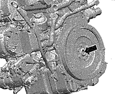
Note: Replace self-locking nuts and screws during assembly work. Replace screws that are tightened to a specified tightening angle, as well as sealing rings and seals. Secure all hose connections with hose clamps in accordance with the serial production condition. All bandages released or cut during removal must be reinstalled in the same places during installation. Always replace the selector lever cable lock washer. Replace needle bearing - see arrow - crankshaft. Check whether there are relief sleeves for centering the gearbox in the cylinder block, install if necessary. When installing the gearbox, pay attention to the correct installation of the intermediate plate between the engine and the gearbox.
Carefully raise gearbox on engine and gearbox jack -VAG 1383 A- and bring gearbox support -3282- into installation position.
Note: When lifting the gearbox, insert the gear selector cable into the cable support. Do not bend or break the control lever cable. Keep an eye on all coolant wires and hoses when lifting the gearbox.
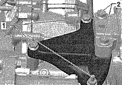
Adjust gearbox mounting -3282- on spindle so that engine and gearbox "were on the same line". Align the engine and gearbox with your hands so that the engine flange is pressed against the gearbox flange around the entire perimeter! If necessary, turn the crankshaft further. Connect gearbox to engine with bolts. Position the assembly support as follows: Insert gearbox bracket -1- between gearbox and support bracket for gearbox support. Screw gearbox bracket -1- to gearbox with new screws. Slowly raise the box on the hooks of the holding device -MP9-200 (10-222 A) - to the bearing bracket of the gearbox support. Tighten the screws first - see arrows by hand.
Carefully! Before screwing in the screws, see arrows - the gearbox console must be strictly parallel to the bearing bracket of the gearbox support, otherwise the threads may be damaged.
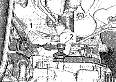
Detach gearbox support -3282- from gearbox. Attach the attachment bracket. Fasten lower power unit support with new bolts -arrows A, B and C- to gearbox. Install the right flange shaft. Install the left and right drive shaft. Install the protective cap of the right drive shaft on the engine, while tightening the screws - see Fig. arrows - torque 35 Nm. Install the fan frame. Connect the charge air hose between the left-hand lower charge air cooler and the charge air pipe. Fasten exhaust pipe bracket to subframe, align exhaust system and relieve tension. Install starter. Check the adjustment of the support of the units. Tighten the new gearbox mounting screws on the gearbox console to the specified tightening torque. Remove retaining device -MP9-200 (10-222 A) -. Carefully install gear selector cable -2- on selector lever and secure with new lock washer -1- on cable support. Install the battery and battery bracket. Check the installation of the control lever cable, adjust if necessary. Install the air filter. Install the left front wheel arch cover. Install the lower engine soundproofing cover. Install front wheels. If the front left vehicle level sender -G78- has been removed, the headlight adjustment must be checked. After installing the gearbox, perform the -Basic setting-.
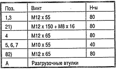
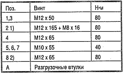
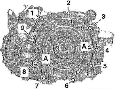
Tightening torques
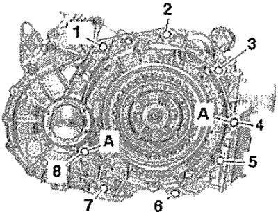
Gearbox attachment for 1.6l/77kW TDI CR engines
 |  |
Gearbox mounting for 1.8 l/132 kW TSI engines
Gearbox mounting for 1.2l/77kW TSI and 1.4l/103kW TSI engines
 | 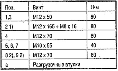 |
1) Additionally starter for gearbox with engine. 2) It is screwed in from the side of the engine.
GB console to GB and GB support to GB console
Replace screws -1- and -2-. Tighten screws -1- to 40 Nm + turn by 90° (¼ vol.). Tighten screws -2- to 60 Nm + turn by 90° (¼ vol.)