
Note: Do not remove the ignition key.
Remove engine cover. Remove air filter. Remove battery and battery bracket. Remove the water box cover. Disconnect the gear selector cable -A- from the selector lever using the door inner trim remover -MP8-602L-.
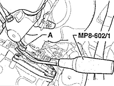
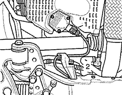
Disconnect the lock washer - see arrow - selector lever cable, leave the gear selector cable in the installation position.
Note: Lock washer - see selector lever cable arrow is always replaced. Do not bend or break the control lever cable. Do not push the selector cable backwards out of the cable support. The selector cable can only be removed from the support when the gearbox is removed.
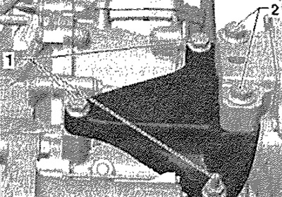
Disconnect the ground wire -1 - from the gearbox console fixing screw. Disconnect the connector and wire from the starter. Loosen the screws - see arrow A- from the starter.
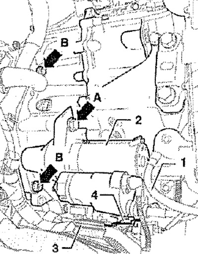
Note: Remove the second fastening screw from the starter (not visible in the picture) and remove the starter -2-.
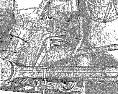
Loosen connecting screws - see Arrows B - Engine/Gearbox To do this, if necessary, use socket -T10035-. Disconnect wiring connectors -3- from holder -4- and tie up. Detach holder -4- from gearbox.
Carefully! Never touch the plug-in contacts in the gearbox connector with your hands, so that a static discharge does not damage the control unit and mechatronics.
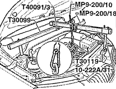
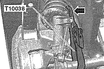
Touch your hand (without gloves) to ground to remove the electrostatic charge. Unlock the mechatronics plug by pulling in the -direction of the arrow- and disconnect the plug. Remove the caps on the threaded connections of the cups of the front suspension struts.
Fit retaining device -T30099- together with other components as shown in illustration. Lightly tension the engine/gearbox assembly on the hooks, but do not lift.
Remove front wheels. Remove the lower soundproofing casing of the engine. Remove the front left wheel arch cover. Disconnect the charge air hose from the left-hand lower charge air cooler and charge air pipe. Disconnect the connector -1 - of the radiator fan. Unclip -arrow B- and remove fan shroud.
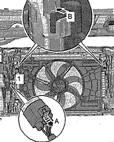
Note: The fan shroud can accommodate two fans.
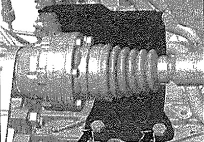
Remove the protective caps of the right cardan shaft from the engine - see. arrows-.
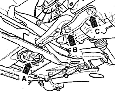
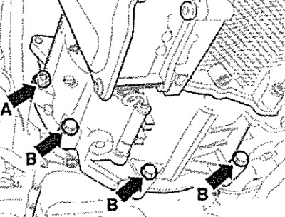
Remove the stabilizer bar strut, to do this, unscrew the screws - see. arrows A, B and C-. Disconnect the exhaust system at the coupler and remove the exhaust system bracket from the attachment bracket. Tie up the exhaust pipe.
Unplug connector -1- for oil level and oil temperature sender -G266-. Release electrical wires from holder -2-.
If present, remove front left vehicle level sender -G78-. Lower the attachment bracket to the maintenance position, Disconnect the drive shafts from the flanges.
Tie up driveshaft as high as possible. In doing so, do not damage the paintwork on the drive shaft. Remove the right flange shaft.
Continuation for vehicles with 1.2l and 1.4l engines
For the 1.4l engine, disconnect the front part of the exhaust system; for the 1.2l engine, you can leave the exhaust system in place.
Further for all vehicles
Unscrew the lower connecting screws - see. arrow A- and -see. arrow B - engine / gearbox.
Loosen screws -1- of gearbox bracket approx. one turn and remove screws -2-.
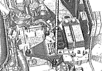
Then lower on the hooks of the holding device -MP9-200 (10-222 A) — the engine and gearbox so that a gap of size -a- is formed between the gearbox console and the gearbox support. Size -a- = 60... 70 mm.
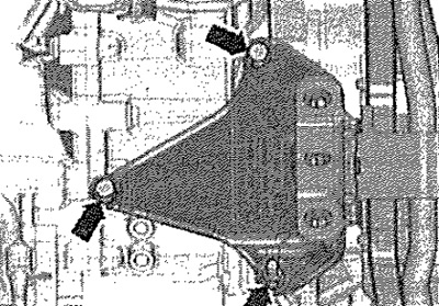
Loosen the screws - see arrows - and remove the gearbox console.
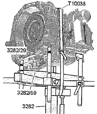
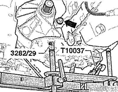
Gearbox holder -3282- for removing gearbox DSG -0CW is equipped with adjusting plate -3282/59- and mounted on engine and gearbox jack -VAG 1383 A-. Align gearbox mounting brackets with holes in adjustment plate -3282/59-. Screw on the fasteners as shown on the adjustment plate -3282/59-. Position engine and gearbox jack -VAG 1383 A- under vehicle. The arrow on the adjusting plate -3282/59- points in the direction of travel. Align gearbox mounting -3282- parallel to gearbox. Screw pin -3282/29- into gearbox. Install both remaining fasteners as shown on the gearbox. In this case, the tip must be located under the gearbox housing, and not under the mechatronics. Secure gearbox with lashing strap -T10038-. Support gearbox from below by raising engine and gearbox jack -VAG 1383 A-.
Remove the last connecting screw - see arrow B- on the engine/gearbox.
Note: Vehicles with 1.2 l/77 kW TSI and 1.4 l/103 kW TSI engines have another connecting screw -3-.
Squeeze out the gearbox from the unloading sleeves. Detach gearbox from engine and lower slightly. When lowering the gearbox, withdraw the gear selector cable from the cable support.
Note: When lowering the gearbox, carefully pull the selector cable out of the cable support. Do not bend or break the control lever cable. Keep an eye on all wires and coolant hoses when lowering the gearbox.
Move the gearbox and fix it on the mounting stand.