



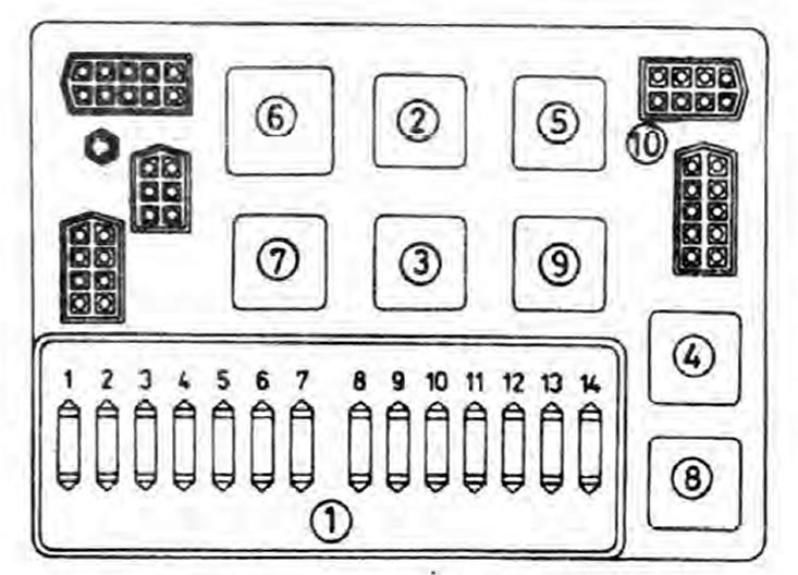
Pic. 12.5. Location of components in the fuse and relay box - models 1989-1992
1. Fuses; 2. Relay - rear fog lights; 3. Relay - front fog lights; 4. Relay - dipped headlights; 5. Relay - spare; 6. Turnip - front wiper breaker; 7. Relay - rear window heater; 8. Relay - high beam headlights; 9. Relay - fuses 2, 3 and 4 (see specs); 10. Terminal block.
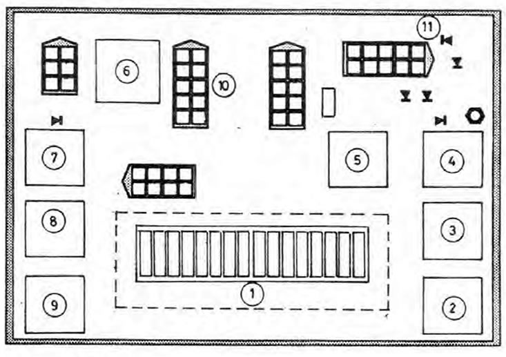
Pic. 12.6. Location of components in the fuse and relay box - models from 1992
1. Fuses; 2. Relay - rear fog lights; 3. Relay - front fog lights; 4. Relay - dipped headlights; 5. Turnip - spare; 6. Relay - front glass cleaner interrupter; 7. Relay - rear window heater; 8. Relay - high beam headlights; 9. Relay - fuses 5, 6 and 7 (see specs); 10. Terminal block; 11. Diode.
Circuit breakers
1. The main fuses are located in the fuse box located in the front passenger's footwell. Early models use ceramic fuses; and on later ones - with flat fusible inserts. Additional fuses can be found in the wiring to some components. The car radio installed by Skoda dealers is protected by its own fuse, which is located in the holder on the car radio.
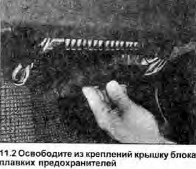
2. The fuses can be accessed by releasing the cover from the brackets (photo).
3. Before removing a fuse, first turn off the circuit it protects (or ignition), and then remove the fuse from its socket. If the fuse is blown, the conductor in it will be melted.
4. Whenever replacing a fuse, use a new one with the same current rating. Replace a fuse only after the problem that caused it to blow has been identified and corrected. The current limit is printed on the top of the fuse; note that the fuses are also color coded.
5. If the fuse blows immediately after replacement, find the cause and correct the problem. In case the fuse protects multiple circuits, try checking each circuit in turn (if it is possible).
6. If a spare fuse is used, always replace it immediately so that a spare of the same rating is available.
Fuse box - removal and installation
Removing
7. Disconnect the negative cable from the battery.
8. Remove the fuse cover.
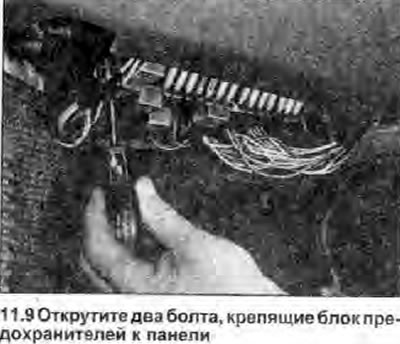
9. Remove the two screws securing the fuse box to the panel (photo), then lower the block to the floor.
10. Disconnect the connectors from the fuse block, carefully noting their location.
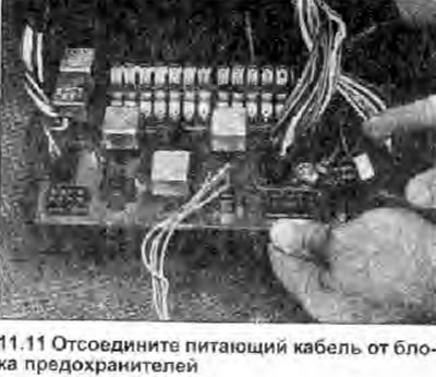
11. Unscrew the terminal nut, and remove the power cable of the fuse box (photo). Remove the fuse box.
Installation
12. Install in the reverse order of removal; make sure the wiring is properly connected and routed.
Relay
13. In Specifications this Section gives complete information regarding the location and function of the various relays; see also «Wiring diagrams».
14. Relay is an electrically operated switch that is used for the following reasons:
- a) The relay can switch high current at a distance, thus allowing the use of thin wiring and switch contacts.
- b) A relay can receive multiple control inputs, unlike a mechanical switch.
- c) Reze can have a function «timer» - for example, a windshield wiper breaker relay.
15. If the relay controlled circuit or system does not work, the relay may be faulty, turn on the system; if the relay is functioning, a click may be heard when it is activated. In this case, the system components or wiring are faulty. If the relay does not work, then either the supply or control voltage is not supplied to it. or the relay is defective. Testing a relay is a matter of substituting a known-good relay, but be careful as some relays may be identical in appearance and operation, while others look similar but perform different functions.
16. To replace the relay, disconnect the negative cable from the battery, then simply remove the old one from the socket and insert the new one (photo). Finally, connect the battery.
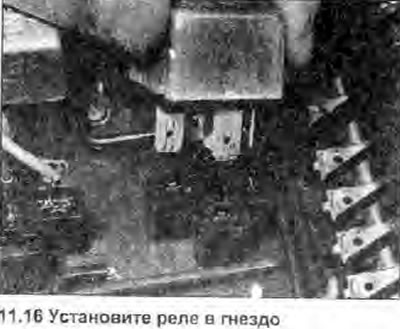
Warning: The socket terminals can be easily damaged if the relay is not installed carefully.
Turn signal and alarm breaker
17. The turn signal and alarm switch can be accessed by removing the central switch panel (Chapter 12) (photo).
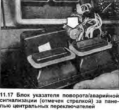
18. Before replacing a suspected broken circuit breaker, make sure that the problem is not a burned out lamp or a bad «mass».