



Contents: Ignition switch ⬇ Multi-function switches on the…⬇ Switches on the dashboard ⬇ Interior Light Switches ⬇ Oil pressure sensor ⬇ Radiator Fan Thermal Switch ⬇ Reverse light switch ⬇ Brake light switch ⬇ Handbrake indicator light switch ⬇
Note: Before removing the switch, disconnect the negative battery cable.
Ignition switch
1. For details on removing and installing the switch, see Section 10.
Multi-function switches on the steering column
Removal
2. Remove the upper and lower steering column covers (Section 10).
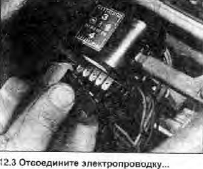
3. Disconnect the wiring connectors from the switch (photo).
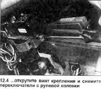
4. Unscrew the mounting screw (photo) and remove the switch.
Installation
5. Install in the reverse order of removal.
Switches on the dashboard
Removal
6. The switches for the headlights, parking lights, rear window defroster and hazard warning lights are located in the central switch panel. Front fog light switches (where is available) and rear fog lamp are located in the auxiliary switch panel. All of them are removed as follows.
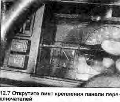
7. To remove the switch panel, unscrew the mounting screw (photo), remove the switch panel and disconnect the electrical wiring.
(Information published on the website SKODABOOK.ru)
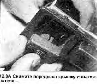
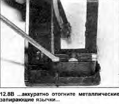
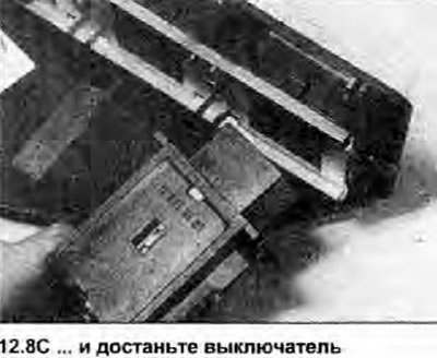
8. To remove the switch from the panel, remove the front cover from the switch, then carefully bend back the four metal tabs and remove the switch from the panel (photo).
 |
 |
 |
Installation
9. Install in the reverse order of removal.
Interior Light Switches
10. The interior lighting is controlled by a switch installed in each (front) door pillar and a switch directly in the lamp assembly.
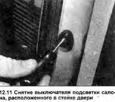
11. To remove the switch from the door pillar, unscrew the mounting screw (photo) and remove the switch, then disconnect the wiring, making sure that the wire does not fall inside the pillar. Install in the reverse order of removal.
12. The switch installed in the ceiling is part of the lantern; for removal and installation follow the instructions Chapter 14 from this Section.
Oil pressure sensor
Removal
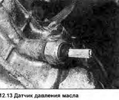
13. The sensor is located on the engine block, next to the oil filter (photo).
14. Disconnect the wiring, then unscrew the sensor; plug the hole in the block with a clean rag to reduce oil loss.
Installation
15. Clean the sensor threads and replace the sealing washer, if any; if there is no sealing washer, apply a small amount of sealant to the threads.
16. Remove the rag from the hole in the block, screw in the sensor and tighten it with the specified tightening force Specifications.
Radiator Fan Thermal Switch
17. See Section 3.
Reverse light switch
18. See Section 7.
Brake light switch
19. See Section 9.
Handbrake indicator light switch
20. See Section 9.