
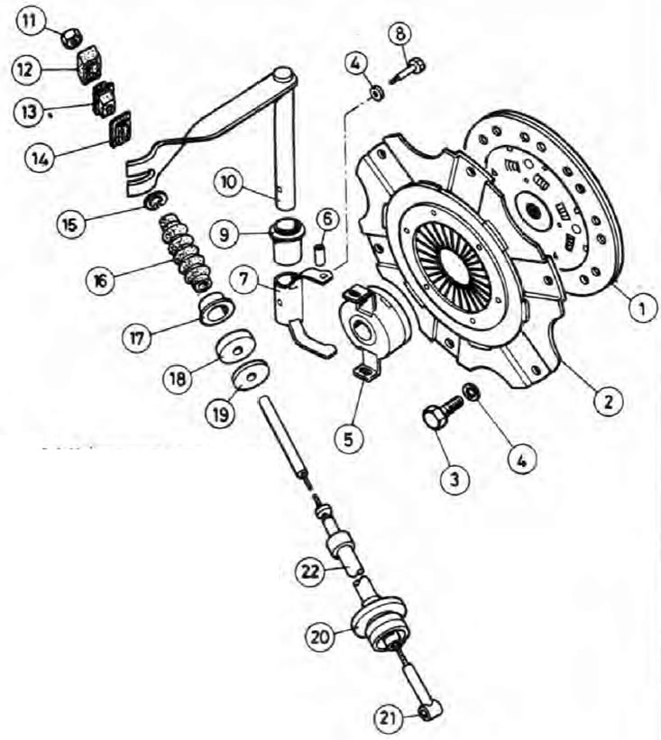
Pic. 6.1. Clutch and Release Components
1. Friction disc; 2. Pressure plate; 3. Bolt of fastening of a pressure plate; 4. Washer; 5. Release bearing; 6. Clutch release fork pin; 7. Clutch release fork; 8. Bolt for the clutch release fork; 9. Sleeve of the lever of a fork of deenergizing of coupling; 10. Clutch release fork lever; 11. Cable adjusting nut; 12. Limiter; 13. Rubber gasket; 14. Limiter; 15. Spring clip; 16. Rubber protective cover; 17. Nest; 18. Rubber seal; 19. Washer; 20. Sealing washer; 21. Blocking bracket; 22. Clutch cable.
The clutch consists of a friction disc, a pressure plate assembly, a release bearing and a release mechanism. All of these components are housed in a large aluminum alloy crankcase sandwiched between the engine and transmission. The release mechanism is driven by a cable.
The friction disc is mounted between the engine flywheel and the clutch pressure plate and can slide on the slots in the transmission input shaft. The disc is equipped with two round friction linings attached to it with rivets (pads form the working surface of the clutch), and a spring-loaded hub that softens the transmission of torque.
The pressure plate assembly is bolted to the flywheel. It includes the clutch housing cover, diaphragm spring and the actual pressure plate. When the engine is running, drive is transmitted from the crankshaft through the flywheel and clutch housing cover to the friction disc (the last three components are securely pressed against each other by a pressure plate with a diaphragm spring), and from the friction disc to the input shaft of the transmission.
To interrupt the drive transmission, the spring pressure must be released. This is achieved by offsetting the release bearing mounted on the transmission input shaft.
When the driver presses the clutch pedal, the release bearing presses on the ends of the sectors of the diaphragm spring in its center. From this, the peripheral part of the spring moves outward, and the clutch pressure plate moves away from the friction plate, disengaging the clutch.
Depressing the clutch pedal pulls a cable attached to it, which in turn turns the clutch fork - it is attached to the upper end of the fork lever, above the clutch housing. The fork itself is attached to the release bearing.
As the lining of the friction disc wears out, the pressure plate moves towards the flywheel; this forces the sectors of the diaphragm spring to press against the release bearing, thus reducing the clearance that must be present in the mechanism. To ensure the correct functioning of the mechanism, it is necessary to periodically adjust the length of the clutch cable as described in Section 1.