
Warning: Dust generated by worn clutch components may contain asbestos, which is harmful to health DO NOT blow dust off components with compressed air and be careful not to inhale particles that are accidentally lifted into the air. DO NOT use benzine or mineral solvents to wash off dust - only a special cleaner or methyl alcohol is suitable for this. Wipe the clutch components with a clean rag
Note: Although some companies make friction linings that do not contain asbestos, it is safer to assume that the linings installed on your car are not the same «harmless» type and take the precautions described above.
Removing
1. The clutch can be reached when the power unit is removed from the vehicle for overhaul (see section 2), or by removing the transmission as described in Section 7.
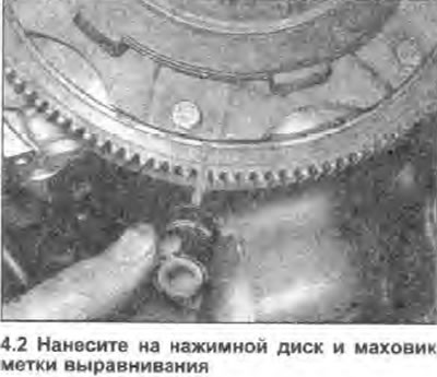
2. Before removing the clutch, mark the pressure plate assembly and flywheel with an alignment mark using a suitable marker or quick dry paint (see photo).
3. In a diagonal sequence, loosen the pressure plate mounting bolts by turning them half a turn at a time. Do this until the spring pressure is relieved, at which point the bolts can be loosened by hand. Remove bolts along with washers.
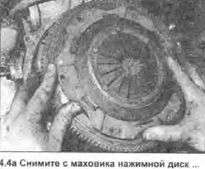
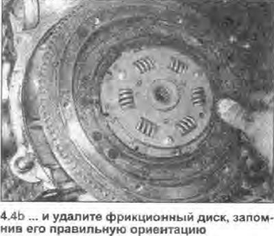
4. Remove the pressure plate assembly from the flywheel and remove the friction plate, noting its correct orientation (see photo).
 |  |
Inspection
Note: Given the length and complexity of accessing clutch components, it is recommended that the friction plate, pressure plate assembly, and release bearing be replaced, even if only one of these components is actually worn.
5. Remove the clutch assembly.
6. See the warning given at the beginning of this Chapters, and clean the clutch components.
7. Check friction disc linings for damage, signs of wear and oil stains. If the pad is cracked, burned, pitted or otherwise damaged, or contaminated with oil or grease (shiny black spots), the friction disc must be replaced.
8. If the friction linings are still serviceable, check. that the grooves of the hub are not worn out, its damper springs are in good condition and securely fastened, and all disc rivets are in place and hold tight. If any damage or signs of wear are found, replace the friction disc.
9. If the friction lining is contaminated with oil, it may be caused by leakage from the left crankshaft oil seal (shaft horses facing the flywheel), sump/cylinder block joint, or transmission input shaft seal. Replace seal or gasket (see Section 2 or 7), before installing a new friction disc.
10. Inspect the pressure plate assembly for damage and signs of wear. Shake the disc to check for loose rivets and worn/damaged diaphragm spring support rings. Check that the plates holding the pressure plate to the clutch cover do not show signs of overheating (bright yellow or blue spots). If the diaphragm spring is worn or damaged, or if its pressure is weakened, the pressure plate assembly must be replaced.
11. Examine the processed working surfaces of a pressure disk and a flywheel: they have to be pure, equal and free from scratches or seizings. If the surface is discolored from overheating or cracked, the component should be replaced, although minor damage of this nature can sometimes be sanded off using sandpaper. Alternatively, have a professional regrind the flywheel (see Chapter 12 Section 2).
12. Check the condition of the release bearing as described in Chapter 5 of this Section.
Installation
13. When assembling, make sure that the working surfaces of the flywheel and pressure plate are absolutely clean, smooth and free from oil and grease. Use a solvent to remove protective grease from new components.
14. Install the friction disc so that the larger part of its hub faces the flywheel. Install the pressure plate assembly, aligning the marks made during removal if the old plate is being installed. When installing a new pressure plate assembly, it can be located anywhere.
15. Install the pressure plate mounting bolts and washers and tighten them only by hand so far, so that the friction plate can still move.
16. Now the friction disc must be centered so that when installing the transmission, its input shaft freely enters the grooves of the disc hub.
17. Insert a screwdriver or other long rod into the hub of the friction disc so that the tool rests against the recess in the crankshaft; then move the disc to the desired side until it is exactly in the center. Alternatively, a special centering tool can be used - available from many auto parts stores. You can also make such a tool yourself. This will require a metal rod or wooden pin, the diameter of which is slightly smaller than the diameter of the recess in the end of the crankshaft. It is necessary to wind an insulating tape on the rod so that a thickening corresponding to the diameter of the splined hole of the friction disk is obtained.
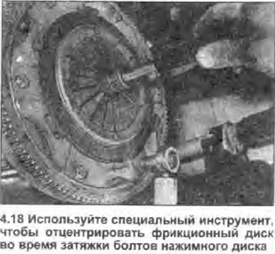
18. After the friction plate is centered, evenly tighten the pressure plate bolts in a diagonal sequence with the tightening torque specified specifications (see photo).
19. Apply a small amount of molybdenum grease to the grooves of the friction disc and transmission input shaft, as well as to the release bearing bore.
20. Install the transmission as described in Section 7.