



Contents: Service technology ⬇ Fasteners ⬇ Fastener dimensions ⬇ Procedure and order of tightening…⬇ Disassembling the components ⬇ Gasket surfaces ⬇ Tips for removing hoses ⬇
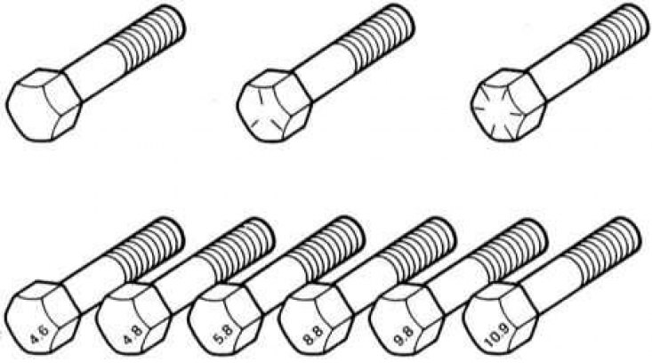
Marking of the strength class of bolts (top - standard /SAE/USS, bottom - metric)
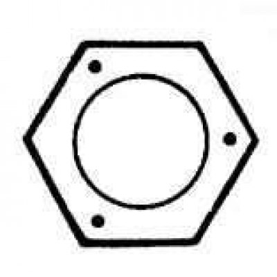
Strength class marking of standard hex nuts
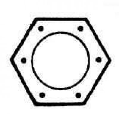
Metric Hex Nut Strength Class Markings
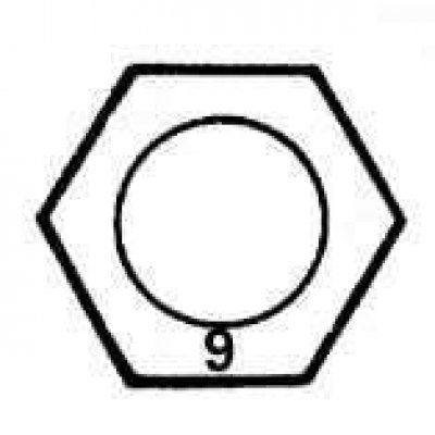
Marking the strength class of metric studs
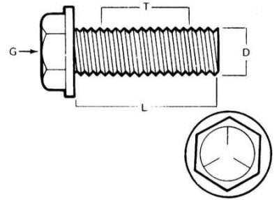
Dimensions/strength class markings for standard (SAE and USS) bolts: G — marking of strength class; L — length (in inches); T — thread pitch (number of threads per inch); D — nominal diameter (in inches)
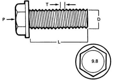
Dimensions/Grade Markings for Metric Bolts: Pm — strength class; L — length (in mm); T — thread pitch (distance between adjacent turns in mm); D — nominal diameter (in mm)
Service technology
There are several methods for performing vehicle maintenance and repair procedures, which the reader will find references to in the text of this Manual. Following them will make the amateur mechanic's work more efficient, will allow the best organization and quality execution of various technical procedures, and will be the key to thorough and complete execution of all necessary work.
Fasteners
Fasteners are nuts, bolts, studs and screws used to connect two or more parts together. When working with fasteners, you must always remember some things. Almost any threaded fastener uses one or another type of locking and locking devices. These can be lock washers, lock nuts, lock flags or thread locking compound. All used fasteners must be absolutely clean and straight, with undamaged threads and unrounded corners of the hexagonal heads onto which the wrench is placed. It is a rule to replace damaged nuts and bolts with new ones without fail. Special self-locking nuts with nylon or fiber inserts cannot be reused, since they lose their locking properties when loosened and must always be replaced during assembly.
"Stuck" fasteners should be treated with a special penetrating compound before loosening to make them easier to unscrew and to avoid damage. Many mechanics prefer to use turpentine for this purpose, which is conveniently applied from a special small canister with a long spout. After wetting the fastener with the penetrating compound, let the compound soak the oxidized contact layer thoroughly for several minutes. Heavily rusted fasteners can be cut off with a chisel, sawed off with a hacksaw, or removed with a special nut splitter.
When a bolt head is sheared off or a stud is broken off on an assembly, the remaining threaded portion can be drilled out or extracted with a special extractor. Most auto repair shops can undertake this, as well as other (for example, restoration of stripped threads in threaded holes), repair procedures.
Flat and lock washers must always be installed in their original positions during assembly. Always replace damaged washers with new ones. Between the lock washer and the soft metal surface (for example aluminum), when using thin sheet metal or plastic, always use flat washers.
Fastener dimensions
For many reasons, vehicle manufacturers are increasingly using metric fasteners. However, it is important to know the difference between the standard (also called American or SAE standard) and more universal in the metric system of measures, since, despite the external similarity, they are not interchangeable.
All bolts, both standard and metric, are classified by diameter, thread pitch, and length. For example, a standard 1/2-13x1 bolt is half an inch in diameter, has 13 threads per inch, and is 1 inch long. A metric M12-1.75x25 bolt has a diameter of 12 mm, a thread pitch of (distance between adjacent turns) 1.75 mm and 25 mm long. Both bolts are almost identical in appearance, but are not interchangeable.
In addition to the above features, both metric and standard bolts can be identified by examining the head. For starters, the distance between the flats on the head of a metric bolt is measured in mm, while a standard bolt is measured in inches (the same is true for nuts). As a result, a standard wrench is not suitable for use with metric fasteners, and vice versa. In addition, most standard bolts usually have radial notches on their heads that determine the maximum allowable tightening force of the bolt (degree of strength). The greater the number of notches, the higher the permissible force (cars typically use bolts with strength classes from 0 to 5). The strength class of metric bolts is determined by a numerical code. The code numbers are usually cast, as on standard fasteners, on the head of the bolt (automobiles typically use bolts of strength classes 8.8, 9.8, and 10.9).
Also, standard nuts can be distinguished from metric nuts by strength class marks. To identify the strength class of standard nuts, dot marks are used, stamped on one of the end surfaces of the nut, while metric nuts are marked using a digital code again. The greater the number of dots, or the greater the value of the digital code, the higher the permissible tightening force of the nut.
The ends of metric studs are also marked according to their strength class. Large studs are marked with a digital code, while smaller ones are marked with geometric shapes.
It should be noted that a significant portion of fasteners, especially those of strength class 0 to 2, are not marked at all. In this case, the only way to distinguish standard fasteners from metric ones is to measure the thread pitch, or compare the thread with a uniquely identified one.
Standard fasteners are often referred to as SAE standard fasteners, as opposed to metric fasteners, but it should be remembered that only small fasteners fall under the SAE classification. Large fasteners with non-metric threads are American Standard Fasteners (USS).
Since the fasteners are of the same geometric size (both standard and metric) may have different strength classes; when replacing bolts, nuts and studs on a vehicle, attention should be paid to ensuring that the strength class of the new fasteners being installed matches the strength class of the old ones.
Procedure and order of tightening threaded connections
Tightening of most threaded connections should be carried out with forces determined by the requirements of the Specifications given at the beginning of each Chapter of this Manual (the tightening force of a fastener should be understood as the torque applied to it when tightening). Overtightening can result in failure of the fastener, while undertightening can result in unreliable connections between the mating components. Bolts, screws and studs, depending on the material they are made of and the diameter of the threaded portion, usually have strictly defined permissible tightening forces, many of which, as mentioned above, are listed in the Specifications at the beginning of each Chapter. Strictly adhere to the recommendations for tightening the fasteners used on the vehicle. For tightening fasteners not listed in the Specifications, use the permissible torque chart below. The values in the table are oriented towards fasteners of strength classes 2 and 3 (higher-grade fasteners allow for greater tightening force), in addition, it is implied that dry tightening is carried out (with ungreased threads) fasteners screwed into steel or cast (not aluminum) detail.
Metric Thread Sizes
| M-6 | 9 -12 Nm |
| M-8 | 19 - 28 Nm |
| M-10 | 38 - 54 Nm |
| M-12 | 68 - 96 Nm |
| M-14 | 109 - 154 Nm |
Pipe thread sizes
| 1/8 | 7 -10 Nm |
| 1/4 | 17 - 24 Nm |
| 3/8 | 30 - 44 Nm |
| 1/2 | 34 - 47 Nm |
American Standard Thread Sizes
| 1/4 - 20 | 9 -12 Nm |
| 5/16 - 18 | 17 - 24 Nm |
| 5/16 - 24 | 19 - 27 Nm |
| 3/8 - 16 | 30 - 43 Nm |
| 3/8 - 24 | 37 - 51 Nm |
| 7/16 - 24 | 55 - 74 Nm |
| 7/16 - 20 | 55 - 81 Nm |
| 1/2 - 13 | 75 - 108 Nm |
A fastener located around the perimeter of a part (such as cylinder head bolts, oil pan bolts and various covers) to avoid deformation of the part, it must be loosened and tightened in a strictly defined order. The order of tightening and loosening such fasteners is given in the relevant Chapters of the Manual. If a special order is not specified, then in order to avoid distortion of the component, the following instructions should be followed. At the first stage, all bolts or nuts should be tightened by hand. Then, each of them in turn should be tightened another full turn, and the transition from one bolt/nut to another should be carried out in a diagonal order (criss-cross). Next, returning to the first bolt/nut, repeat the procedure in the same order, tightening the fastener another half turn. Continue the procedure, tightening each bolt/nut this time by a quarter turn at a time until they are all tightened to the required force. When loosening the fastener, proceed in a similar manner, but in reverse order.
Disassembling the components
Disassembly of all components must be carried out in such a manner that during assembly each part can be installed in its original place and in the correct way. Remember the characteristic external features of the unit, if necessary, make a landing marking of parts, the installation of which in place can be carried out in an ambiguous way (for example, a grooved thrust washer on a shaft). It is a good idea to lay out the removed parts on a clean work surface in the order in which they were removed. It may also be helpful to make simple schematic drawings or take step-by-step photographs of the component to be removed.
When releasing fasteners, try to mark their original position on the assembly. Often, installing fasteners and washers in their original place immediately after removing the corresponding part helps to avoid confusion during assembly. If this is not possible, all fasteners should be placed in a specially prepared box, divided into sections and appropriately marked, or simply in separate marked boxes. This procedure is especially useful when working with components consisting of many small parts, such as a carburetor, generator, valve mechanism, instrument panel or decorative trim elements.
When disconnecting electrical contacts and connectors, pay attention to marking the wires or harnesses using tape with a digital or letter code applied to it.
Gasket surfaces
On all vehicles, sealing gaskets are used to seal the junction of the mating surfaces of two or more parts and serve to prevent oil and liquid leaks and maintain increased pressure or vacuum inside the assembly.
Often such gaskets are coated with a liquid or paste-like sealing compound before installation (sealant). Often, under the influence of time, temperature or pressure, the mating surfaces become so strongly "stuck" to each other that separating the parts becomes a difficult task. In many cases, successful dismemberment of such units is assisted by tapping the components from the outside along the perimeter of the joint with a soft-faced hammer. You can also use a regular hammer for this purpose, striking through a wooden or plastic spacer. Do not tap cast housings or fragile components. If such difficulties arise, always first check whether all fasteners have been removed.
Avoid levering the parts with a screwdriver or pry bar inserted into the joint area, as the sealing surfaces can easily be damaged, which will lead to leaks later. If levering the "stuck" assembly elements cannot be avoided, use the handle of an old broom for this purpose, but remember that all the splinters that form must be carefully removed from both the mating surfaces and from inside the assembly.
After separating the parts, their mating surfaces should be carefully cleaned, scraping off any traces of the old gasket material. Hardened fragments can be softened in advance with a rust converter or special chemical compound, and then removed from the mating surface with a scraper. In this case, a piece of copper tube with a flattened and sharpened end can be used as a scraper. It is recommended to use a copper tube for this purpose, since copper is usually softer than the materials used in cars, which reduces the risk of damaging the mating surface. Some gasket residues can easily be removed with a copper brush, but regardless of the method used, the mating surfaces must be completely clean and dry. If for any reason the mating surface is damaged, fill the defects with gasket sealant before assembling the components. In most cases, a non-hardening gasket sealant should be used (or partially solidified) sealant.
Tips for removing hoses
Caution! If your vehicle is equipped with an air conditioning system, do not disconnect any hoses from the system components under any circumstances until the circuit has been discharged at an authorized Skoda service station or by an air conditioning specialist.
The precautions to be taken when removing hoses are very similar to those when dismantling gaskets. Avoid damaging the surfaces of the fittings and pipes onto which the ends of the hoses are pulled, as this may cause leaks to develop. The latter applies especially to the procedure for removing radiator hoses. Due to various chemical reactions occurring in the cooling system, the rubber of the hoses often "sticks" to the mating surfaces of the fittings and pipes. To remove a hose, first loosen the clamp securing it to the fitting. Then use pliers to grasp the hose near the clamp and begin to rotate it on the fitting/connecting pipe to the right and left. Continue the procedure until the hose is completely free, then remove the hose from the fitting. A small amount of silicone or other grease introduced into the gap between the fitting and the hose will facilitate the work. Before installing the hose, lubricate the inner surface adjacent to the end, as well as the outer surface of the fitting with a solution of soapy water or a small amount of silicone grease.
As a last resort, or in case of a clear need to replace the hose with a new one, the end of the hose put on the nipple can be cut with a knife and then separated from the surface of the nipple. In doing so, try not to damage the metal of the nipple/connecting pipe with the knife.
If the hose clamp is damaged, replace it with a new one. Twist-type clamps tend to loosen over time, so regardless of their condition, it is best to replace them with screw-type clamps when necessary.