



Contents: Cylinder block ⬇ Crankshaft and intermediate shaft ⬇ Connecting rod and piston group ⬇ Cylinder head ⬇ Water pump ⬇
Cylinder block with main components of the crankshaft
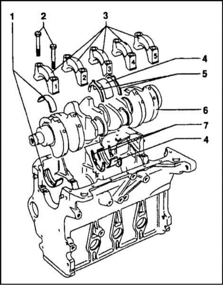
1 - First main bearing shell; 2 - Main bearing cap mounting bolts; 3 - Main bearing caps; 4 - Third (thrust) main bearing shells; 5 - Lower thrust half rings; 6 - Crankshaft; 7 - Lower thrust half rings
Cylinder block with crankshaft mounting components
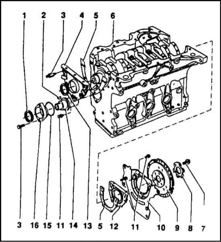
1 - Seal; 2 - Segment key; 3 - Mounting pin; 4 - Front cover; 5 - Sealing gasket; 6 - Cylinder block; 7 - Bolt; 8 - Flange; 9 - Flywheel; 10 - Back cover; 11 - Bolt; 12 - Rear oil seal holder; 13 - Seal; 14 - Intermediate shaft; 15 - Sealing ring; 16 - Oil seal holder
Connecting rod and piston assembly
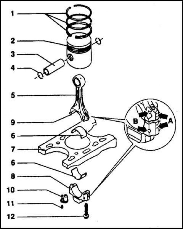
1 - Piston rings; 2 - Piston; 3 - Piston pin; 4 - Retaining rings; 5 - Connecting rod; 6 - Connecting rod bearing shells; 7 - Cylinder block; 8 - Connecting rod lower head cover; 9 - Mounting pin; 10 - Oil jet; 11 - Bolt; 12 - Bolt
Cylinder head with valve train and timing drive components
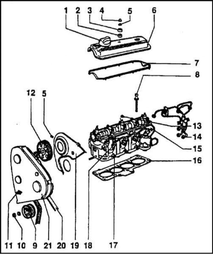
1 - Oil filler cap; 2 - Seal; 3 - Washer; 4 - Nut; 5 - Washer; 6 - Cylinder head cover; 7 - Lid sealing gasket; 8 - Head mounting bolt; 9 - Tension roller; 10 - Nut; 11 - Plank; 12-Gear camshaft wheel; 13 - Lower seal of cylinder head mounting stud; 14 - High pressure pipelines; 15 - Cylinder head; 16 - Head sealing gasket; 17 - Glow plug; 18 - Fuel injection nozzle; 19 - Lid; 20 - Timing belt; 21 - Timing belt cover
Components of the camshaft and valve train installation
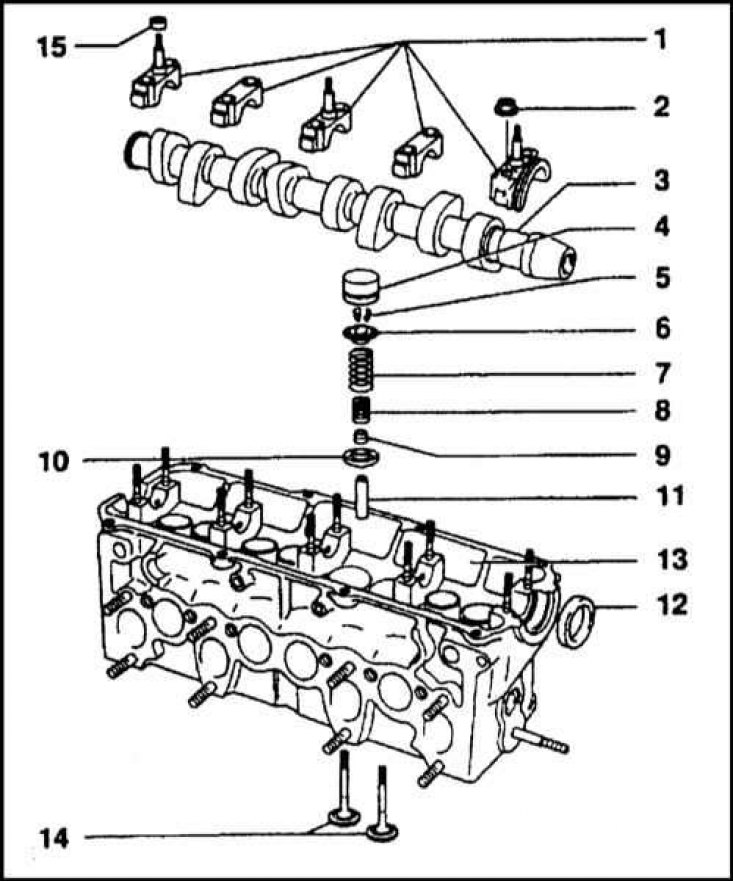
1 - Camshaft bearing caps; 2 - Nut; 3 - Camshaft; 4 - Hydraulic pusher; 5 - Split lock crackers; 6 - Valve spring plate; 7 - Outer valve spring; 8 - Inner valve spring; 9 - Oil deflector cap; 10 - Washer; 11 - Guide bushing; 12 - Seal; 13 - Cylinder head; 14 - Valves; 15 - Seal
Side section of the cylinder head
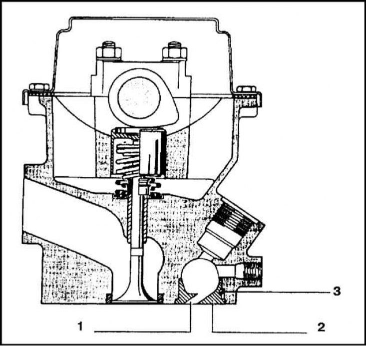
1 - Vortex chamber channel; 2 - Vortex chamber; 3 - Pin for fixing the position of the vortex chamber
Water pump
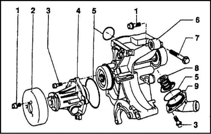
1 - Bolt; 2 - Pulley; 3 - Bolt; 4 - Water pump; 5 - Sealing ring; 6 - Bracket; 7 - Adjusting bolt; 8 - Thermostat; 9 - Thermostat housing
[The original can be viewed on www.skodabook.ru]
Cylinder block
The cast iron block has bores for the cylinders and five main bearings for the crankshaft. The general appearance and installation order of the cylinder block components are shown in the illustrations. The main bearing caps are attached to the block body with special M10 bolts. The third (middle) main bearing is a thrust bearing, it takes up the axial loads that arise and limits the longitudinal play of the shaft.
Crankshaft and intermediate shaft
The crankshaft is forged from steel. The journals of the main and connecting rod bearings are carefully polished. The front journal of the shaft has places for the seating of the timing belt toothed wheel and the sealing gland of the first main bearing. In addition to the crankshaft and distribution shaft, the engine also has an intermediate shaft that transmits rotation from the crankshaft to the oil and vacuum pumps.
Connecting rod and piston group
Forged connecting rods have an I-section and a straight cut of the lower head. A bronze bushing is pressed into the upper head. The lower head is cut in the middle and equipped with connecting rod bearing liners. The correct relative position of the connecting rod cap and connecting rod bearing liners is indicated by punched marks (A). When installing on the engine, the connecting rod should be turned forward with marks (B). The connecting rod bearing cap is fastened to the lower head with bolts. During major repairs, it is customary to replace the bolts fastening the connecting rod bearing caps.
The pistons are cast from an aluminum alloy and have a flat bottom with a recess under the swirl chamber. When installing new connecting rod and piston assemblies, the piston protrusion value above the cylinder block surface should be checked in order to determine the required gasket thickness. If the piston protrusion value is from 0.66 to 0.86 mm, a gasket with one mark is installed. If the protrusion value is 0.87÷0.90 mm - with two, and finally, if the protrusion value is 0.91÷1.02 - with three. When selecting a gasket, the protrusion value of each piston should be checked. The maximum result is taken as a starting point.
The piston pin has a floating fit. Before installing the pin, the piston should be heated to a temperature of 60°C. The pin is fixed by means of two retaining rings.
The piston wall has three grooves for installing piston rings. Two compression rings are installed in the upper grooves, and an oil scraper ring in the lower groove. During vehicle operation, the gaps in the locks of the upper compression and oil scraper rings may widen to 1.2 mm, and the lower compression ring to 0.6 mm. The maximum permissible lateral play of the compression rings is 0.25 mm, and of the oil scraper ring, 0.15 mm. When installing the rings on the piston, the locks are turned at an angle of 120° so that neither lock is on the axis of the piston pin.
Cylinder head
The general appearance of the cylinder head with the valve train components is shown in the illustration. The head is attached to the block with ten TORX-type head bolts. The bolt tightening sequence is similar to that described for the 1.6 l petrol engine.
The head cover is placed on studs screwed into the camshaft supports and secured with three nuts.
The camshaft is placed in five supports and is located directly above the valves. The valves are driven by tappets equipped with hydraulic valve clearance compensators.
The valve guides and seats are pressed into the head and are replaceable components.
The valves are installed vertically and have a row arrangement. Each valve is equipped with two springs, which rest with their lower ends on the support washer, and with their upper ends on the plate. The spring plate is fixed on the valve with split lock crackers.
The camshaft cam does not hit the tappet exactly in the center, which causes the valve to rotate during movement.
The valves undergo special treatment at the manufacturing plant and do not require additional grinding. If defects are detected, the valves (and their saddles) are subject to replacement.
The steel camshaft rotates in five plain bearings that are not equipped with replaceable liners. The camshaft (and fuel injection pump) are driven by a toothed belt transmission. The tension force of the toothed belt is adjusted automatically by a hydraulic tensioner. The belt is replaced after removing the engine from the car. When installing the belt, it is necessary to align the marks on the crankshaft gear and the cylinder block/flywheel and clutch dome, as well as the camshaft gear and belt cover, the fuel injection pump gear and the mounting flange.
The cast cylinder head cover has an oil filler neck equipped with a hermetically sealed threaded plug. The bottom of the filler neck opening is closed with an oil deflector. Three nuts are used to attach the cover to the head, closed on the outside by decorative rubber or plastic plugs.
Water pump
The water pump is designed differently from those used in petrol engines. The pump is mounted on a bracket to which the thermostat housing with the outlet pipe is attached.