
General information
The main function of the toothed belt is to drive the camshaft from the crankshaft. In parallel, the belt is also used to drive the injection pump and the intermediate shaft of the engine. A slipping or broken timing belt while the engine is running can cause severe internal damage to the cylinder head due to valve contact with the piston crowns.
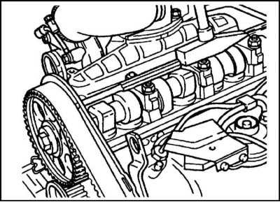
In view of the foregoing, it is extremely important to regularly check the correct adjustment of the belt tension and its general condition. These checks can only be carried out after the belt covers have been removed.
Removing the rear (internal) timing belt cover section is included in the procedure for replacing the camshaft oil seal (see Section Camshaft oil seal replacement).
Removing
1. Before proceeding with the procedure, the engine and vehicle should be immobilized:
- a) Disconnect the negative cable from the battery.
- b) Chock the rear wheels of the vehicle and apply the parking brake. Move the manual transmission control lever to the neutral position.
2. In order to provide better access to the outer covers, remove the air cleaner from the mudguard, and also disconnect the air cleaner from the intake manifold cover (see chapter Supply system).
3. Hang the engine with a winch, or by supporting it with a hydraulic jack (in order to distribute the load, a wooden block should be laid between the head of the jack and the oil pan).
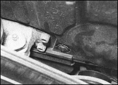
4. In several steps, loosen and unscrew the fixing bolts and remove the right and rear supports of the power unit from the vehicle (see Section Supports of the power unit - check and replacement). Also unbolt the lower part of the right support from the cylinder head.
5. Bring the engine to the TDC position of the end of the compression stroke of the piston of the first cylinder (see Section Bringing the piston of the first cylinder to the top dead center position (TDC) end of compression stroke).
6. Remove the accessory drive belt (see Section Removing, installing and adjusting the tension of the auxiliary drive belt).
7. Lower engine slightly, leaving room to remove auxiliary drive belt pulleys.
8. Turn out fixing bolts and remove pulleys of the water pump and a cranked shaft from the engine.
Note. To ensure reliable blocking of the pulley in the process of releasing the bolts of its fastening, engage a higher gear (do not forget to shift back to neutral after removing the pulley) and have an assistant depress the foot brake pedal firmly. You can also use a rubber cord/old drive belt by wrapping it tightly around the pulley.
9. Turn out a bolt of fastening of a roller of a tensioner of an auxiliary driving belt (the bolt has a left-hand thread!). Remove the roller.
10. Release the metal wire retainers.
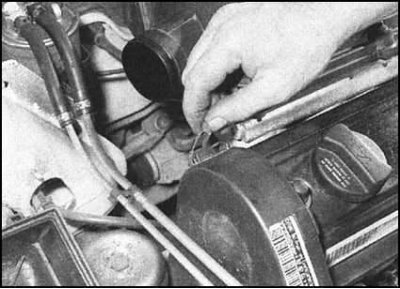
and unscrew the bolt securing the upper cover of the timing belt.
11. Release from a clamp on a cover fuel tubes and take them aside. Remove the upper belt cover from the engine.
12. Turn out bolts, release clamps and remove the bottom cover of a belt.
13. Check the tight fit of the locking pin of the gear wheel of the injection pump (see Section Bringing the piston of the first cylinder to the top dead center position (TDC) end of compression stroke), then loosen the three outer wheel bolts half a turn.
Note. Do not loosen the central wheel nut, as this will violate the basic settings of the injection pump.
14. Loosen the tension of the gas distribution belt by slightly releasing the tensioner mounting nut for this.
15. Check up a belt on presence of factory indexes of a direction of rotation. If necessary, apply the appropriate marking yourself (if, of course, the belt is in satisfactory condition and is subject to further use).
16. Trying not to excessively bend or twist, remove the belt from the gears.
17. Check the belt for traces of contamination with coolant or oil. If any are found, try to immediately identify the source of the leak and eliminate its cause. Particular attention should be paid to the condition of the leading edges of the teeth on the working side of the belt. A worn, dirty or defective belt must be replaced.
Note. Every 50,000 km (30,000 miles) mileage the belt should be changed regardless of its condition.
18. If the belt is not immediately installed back, a warning plate should be hung on the engine in order to prevent accidental rotation of its shafts. For a guarantee, you can seal the ignition lock just in case.
Installation
1. Make sure that the crankshaft is in the TDC position of the end of the compression stroke of the piston of the first cylinder (see Section Bringing the piston of the first cylinder to the top dead center position (TDC) end of compression stroke).
2. Loosen the camshaft sprocket bolt half a turn. Gently tapping on a drift inserted into a specially provided hole in the inner belt cover, loosen the wheel fit on the camshaft cone bearing.
3. Observing the direction of rotation required according to the marking, freely throw the gas distribution belt over the crankshaft gear wheel.
4. Enter the belt into engagement with the teeth of the crankshaft wheel, then put it on the gears of the camshaft and injection pump. Make sure the belt is properly seated on the gear wheels.
Note. It is possible that in order to achieve the adequacy of the belt fit, it will be necessary to slightly correct the position of the gears of the camshaft and injection pump.
5. Avoiding twisting, get the belt with the smooth side under the rollers of the intermediate shaft and tensioner.
6. Make sure that the front of the belt is taut, and that all the slack falls on the area under the tensioner pulley.
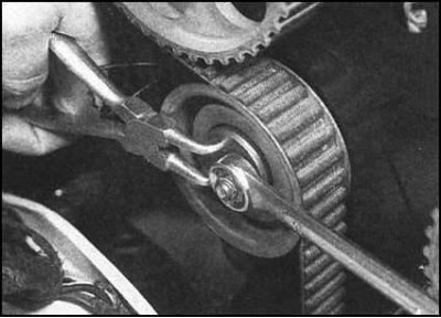
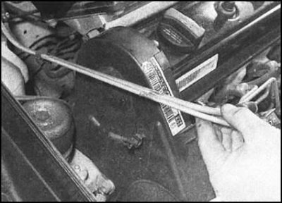
7. Tension the belt by turning the eccentric tensioner clockwise - there are two holes in the tensioner hub specifically for this purpose, into which the ends of circlip removal/installation pliers can be inserted, which are an excellent equivalent of a special Skoda branded tool.
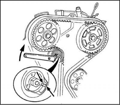
...continue to rotate the tensioner until the landing marks in the form of a risk and a ledge are aligned with each other. After completing the adjustment, tighten the locknut to the required torque.
8. Now once again make sure that the crankshaft is still in the TDC position of the end of the compression stroke of the piston of the first cylinder (see Section Bringing the piston of the first cylinder to the top dead center position (TDC) end of compression stroke).
9. Tighten the camshaft sprocket bolt to specification (see Section Removal and installation of the tensioner and gears of the timing belt).
10. Tighten the three outer bolts of the injection pump gear, then remove the locking pin.
11. Remove the camshaft lock (see Section Bringing the piston of the first cylinder to the top dead center position (TDC) end of compression stroke).
12. Using a socket wrench, turn the crankshaft two full turns on the gear bolt, again stopping it at the TDC position of the end of the compression stroke of the piston of the first cylinder. Make sure that the locking pin can be inserted into the injection pump gear (see Section Bringing the piston of the first cylinder to the top dead center position (TDC) end of compression stroke). Make sure that the timing belt tension is correct, if necessary, repeat the adjustment.
13. Check the correct functioning of the tensioner (see Section Removal and installation of the tensioner and gears of the timing belt).
14. Reinstall the lower and upper sections of the outer timing belt cover. Snap the latches and firmly tighten the mounting bolts.
15. Reinstall the accessory drive belt tensioner roller and tighten the bolt of its fastening (with left hand thread!) with the required effort.
16. Establish a pulley of the water pump, tighten fixing bolts with the demanded effort.
17. Install the auxiliary belt pulley on the crankshaft gear, then, proceeding as in the case of removal, tighten the bolts of its fastening with the required force.
Note. The asymmetric arrangement of the mounting holes provides for the unambiguous installation of the pulley.
18. Reinstall the accessory drive belt and adjust its tension (see Section Removing, installing and adjusting the tension of the auxiliary drive belt).
19. Raise the engine, ensuring that the right and rear power unit mounts can be connected.
20. Reinstall the supports and tighten the bolts of their fastening with the required force. Finally, disconnect the lifting rigging/remove the jack from under the engine.
21. Connect the air intake sleeve to the intake manifold cover and wheel arch mudguard.
22. Connect the negative wire to the battery.
23. In conclusion, check the correctness of the basic settings of the injection pump (see chapter Supply system).