Note: If the drive shaft mounting bolt is loosened by more than 90°, the wheel bearing must not be loaded with the weight of the vehicle, i.e. the vehicle must not be on wheels. If the wheel bearing is loaded with the weight of the vehicle when the drive shaft mounting bolt is unscrewed, the inner bearing will be damaged, which will lead to a reduction in its service life. If the vehicle is to be mounted on wheels or moved, the following must be observed: Install an outer joint instead of the drive shaft. Tighten the mounting bolt (use old) outer CV joint with a torque of 120 Nm.
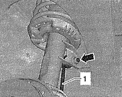
Remove wheel. Unscrew nut -arrow- and remove stabilizer link -1- from suspension strut.
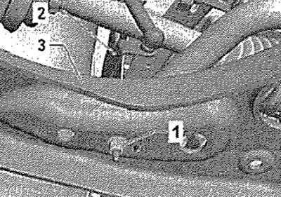
On vehicles with automatic headlight range control, unscrew nut -1- for front left vehicle level sender -G78-.
Unscrew securing nuts -arrows-.
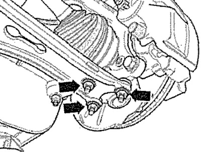
Remove driveshaft outer joint from wheel hub. Tie the drive shaft to the body with wire.
Note: The drive shaft must not hang down, as this will damage the inner joint.
Screw the ball joint back onto the triangular link. Screw engine and gearbox jack -VAG 1383A- together with support -T10149- to hub with wheel bolt. Remove bolt connecting steering knuckle to shock absorber strut -arrow-.
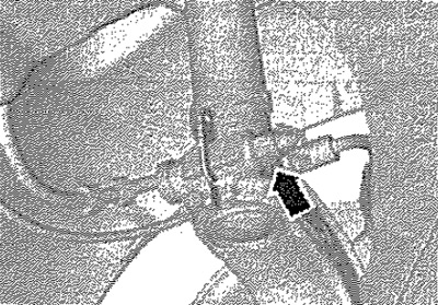
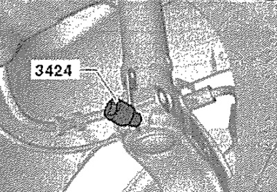
Insert spacer -3424- into opening in steering knuckle.
Turn it 90°with the ratchet wrench and remove the wrench from the spacer -3424-. Press the brake disc in the direction of the shock absorber by hand. Otherwise, the shock absorber may be misaligned in the steering knuckle hole. Remove the shock absorber strut from the steering knuckle hole by pulling it down. The steering knuckle must be lowered with a jack for engines and transmission units, e.g. -VAG 1383A- until the shock absorber strut is completely out of the steering knuckle hole. Tie up the steering knuckle with wire. Place engine and gearbox jack -V, AG 1383A- under the steering knuckle. Remove plenum box cover.
Installation
Install suspension strut, making sure both arrows -arrows- point parallel to the longitudinal axis of the vehicle.
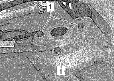
Tighten bolts securing upper damper support -1-. Install the plenum box cover.
Screw engine and gearbox jack -VAG 1383A- together with support -T10149- to hub with wheel bolt. Install the shock absorber on the steering knuckle. Untie the wire from the steering knuckle. Raise the steering knuckle with a jack until the strut-to-knuckle bolt can be inserted. While lifting, press the brake disc in the direction of the shock absorber by hand. Otherwise, the shock absorber may be misaligned in the steering knuckle hole. Remove spacer -3424-. Tighten bolt for shock absorber in steering knuckle -arrow-. Remove nuts -arrows-. Detach the wishbone from the ball joint. Insert the drive shaft into the wheel hub. Install the ball joint with the steering knuckle on the triangular lever. Screw ball joint to triangular link -arrows-.
Note: Check the ball joint boot for damage and creases.
Attach the wire from the ABS sensor to the shock absorber. Insert into the shock absorber and secure the stabilizer bar. Tighten the bolt securing the drive shaft to the hub. Tighten the wheel bolts.
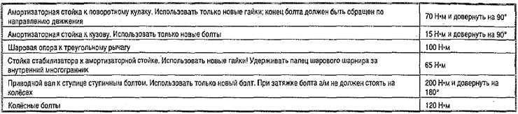
Tightening torques