
Note: If the drive shaft mounting bolt is loosened by more than 90°, the wheel bearing must not be loaded by the weight of the vehicle, i.e. the vehicle must not be on wheels. If the wheel bearing is loaded with the weight of the vehicle when the drive shaft mounting bolt is unscrewed, the inner bearing will be damaged, which will lead to a reduction in its service life. If the vehicle is to be mounted on wheels or moved, the following must be observed: Install an outer joint instead of the drive shaft. Tighten the mounting bolt (use old) outer CV joint with a torque of 120 Nm.
Remove the bolt securing the drive shaft to the hub. Remove wheel. Remove the bracket for the brake pipe and electrical wire and lay it aside. Remove the bracket with the brake caliper and tie it with wire to the body. Remove the speed sensor for the ABS system. Remove brake disc. Remove the shield from the steering knuckle. Loosen the tie rod end nut a few turns, but do not remove it.
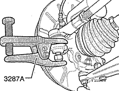
Note: To protect the thread, leave the ball joint nut screwed onto the top few threads of the pin.
Using ball joint extractor -3287A-, press ball joint out of steering knuckle. Now you can unscrew the nut. Pull the drive shaft out of the wheel hub as far as possible (towards the CP).
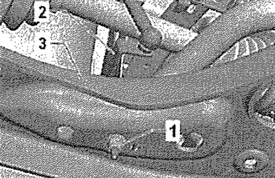
On vehicles with automatic headlight range control, unscrew nut -1- for front left vehicle level sender -G78-.
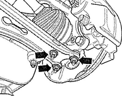
Unscrew securing nuts -arrows-. Press ball joint out of wishbone. Place engine and gearbox jack -VAG 1383A- under steering knuckle.
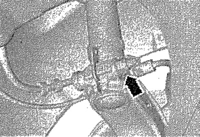
Remove bolt connecting steering knuckle to shock absorber strut -arrow-.
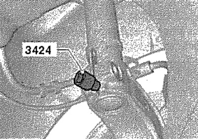
Insert spacer -3424- into opening in steering knuckle. Turn it 90°with a ratchet wrench and remove the wrench from spacer -3424-. Remove the steering knuckle from the shock absorber.
Installation
Installation in reverse order. Tighten the bolt securing the drive shaft to the hub. After replacing the steering knuckle, it is necessary to adjust the wheel alignment angles.