
Note: For assembly work, secure engine to engine and gearbox stand -VAS 6095-.
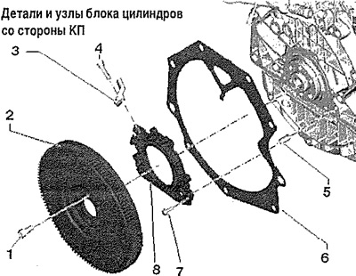
1. 60 Nm and tighten by 90° (1/4 vol.): replace
2. Handwheel: Mounting possible in one position only
3. Engine speed sender -G28-
4. 5 Nm
5. Landing pin, 2 pcs.
6. Intermediate plate: prevent damage or bending during reinforcement work
7. Bolt
8. Cap with drive rotor and lip seal: replaceable only as an assembly with lip seal and drive rotor
Crankshaft cover on the gearbox side - torque and tightening order
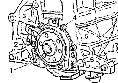
Tighten the screws in stages as follows.

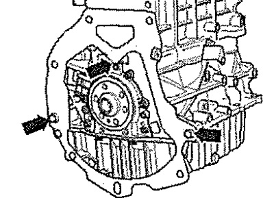
Install intermediate plate
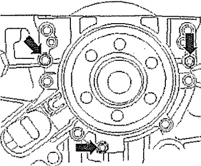
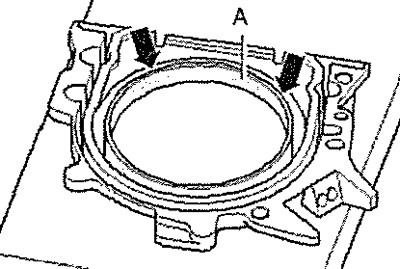
Position spacer on crankshaft cover -upper arrow- and on dowel sleeves -lower arrows-.
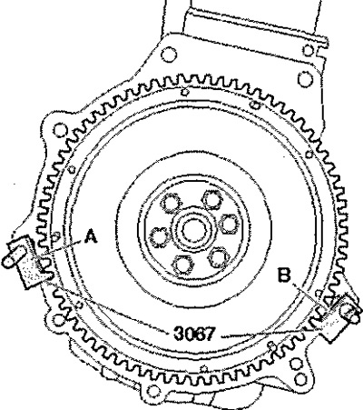
Removal and installation of a flywheel
CP removed. Insert stop -3067- into hole in cylinder block -B-. Loosen the flywheel bolts and remove them.
Installation
Installation in reverse order.
Note: Replace screws that are tightened to the specified angle. The installation of the flywheel with the master rotor is only possible in one position.
Insert stop -3067- into hole in cylinder block -A-.
Torque

Removing and installing the crankshaft cover on the gearbox side
CP removed.
Note: For a better overview, the procedure is shown with the engine removed.
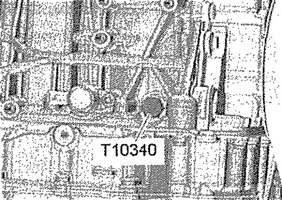
Remove flywheel. Turn the crankshaft to TDC" in the following way. Unscrew the screw plug of the hole "TDC" on the cylinder block. Screw locking bolt -T10340- into cylinder block as far as it will go and tighten to 30 Nm. Turn the crankshaft in the direction of engine rotation as far as it will go. The counterweight of the crankshaft is now adjacent to the locking bolt.
Note: The locking bolt -T10340- only locks the crankshaft in the working direction of rotation.
Carefully! Risk of engine damage! If the locking bolt -T10340- cannot be screwed in completely, the crankshaft is not in the correct position. In this case, proceed as follows.
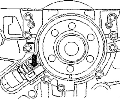
Loosen the lock screw. Rotate crankshaft 90°in direction of engine rotation. Screw locking bolt -T10340- into cylinder block as far as it will go and tighten to 30 Nm. Turn the crankshaft further in the direction of engine rotation until it stops. Remove oil pan. Remove engine speed sender -C28- -arrow-.
Release screws -1...6-.
Note: The cover is pressed off the crankshaft together with the input rotor.
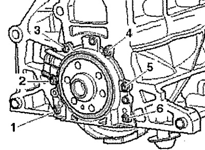
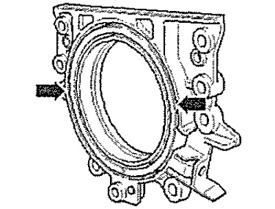
To press out, turn screw M6x35 -arrows- into crankshaft cover 3, alternately tightening each by no more than V2 turns. Remove the cover with the master rotor.
Pressing in the cover with the master rotor
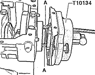
Note: The crankshaft cover with PTFE lip seal is supplied with a support ring for the sealing lip. Do not remove this ring before installation, because. when installed, it will play the role of a mandrel. After removing the cover with the master rotor from the package, do not remove the rotor from the cover and do not turn it relative to the cover. The correct installation position of the feed rotor is ensured by the fixing device -T10134-. The bonnet, lip seal and drive rotor form a single unit and should only be replaced as an assembly. The correct installation position of the tool -T10134- is ensured by the locating pin which engages in the threaded hole in the crankshaft.
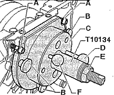
Installing tool -T10134-
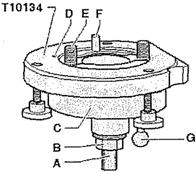
A. Lead screw flat
B. Nut
C. Housing
D. Retainer
E. Hex socket screw
F. Guide pin for diesel engines (black pen)
G. Guide pin for gasoline engines (Red pen)
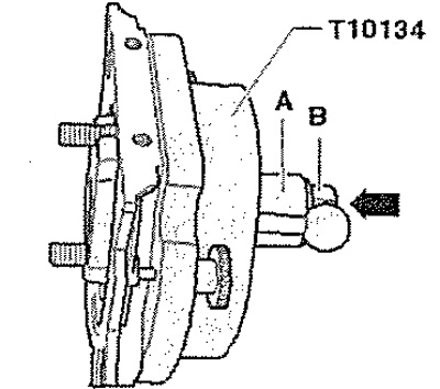
A. Place cover with input rotor on assembly tool -T10134-
Screw on the nut -B- almost up to the flat -A- of the spindle shank. Use a vice to clamp the assembly tool -T10134- in the area of the clamping surface -A- of the spindle. Push housing -C- down until it rests on nut -B- -arrow-. The interior and body of the fixture must be on the same level.
Remove safety catch -arrow- from new crankshaft cover.
Note: Do not turn the drive rotor out of the crankshaft cover.
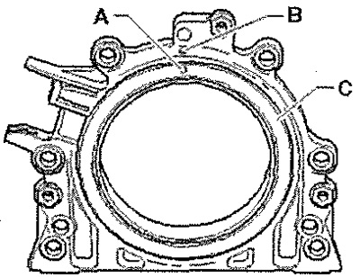
The locking hole -A- on the drive rotor -C- must be opposite the mark -B- on the crankshaft cover.
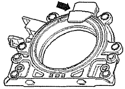
Place the lid on a clean, flat surface on the front (outdoor) side down. Press support ring -A- down in -arrow- until it rests on a level surface.
The upper edge of the support ring and the front edge of the crankshaft cover must be flush -arrows-.
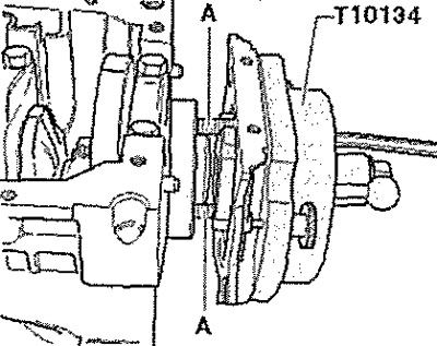
Place the cover with the front side on the tool -T10134- so that the locking pin -B- engages in the hole -A- of the feed rotor. The cover must lie flat on the mounting fixture.
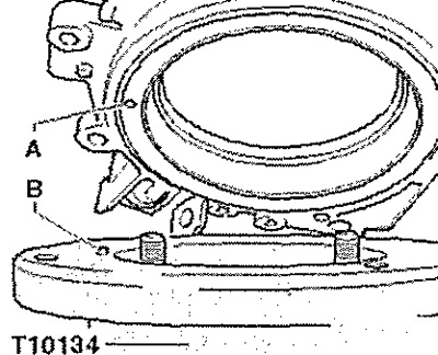
Tighten the 3 knurled screws -A- while pressing the cover and support ring -B- against the surface of tool -T10134- at all times so that the locking pin cannot slip out of the hole in the feed rotor.
Note: When fitting the cover, the feed rotor must remain locked in the mounting device at all times.
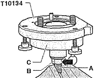
B. Installing tool -T10134- with cover on crankshaft flange
The crankshaft flange must be degreased. The crankshaft is at TDC". Loosen nut -B- to the end of the spindle. Press spindle of tool -T10134- in -arrow- until nut -B- rests against housing -A-. Align the flat side of the housing with the mating plane of the cylinder block on the sump side.
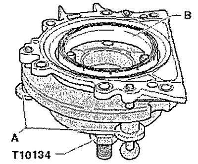
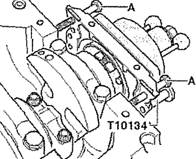
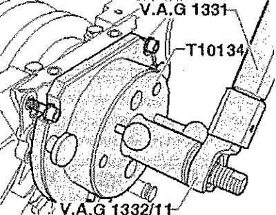
Attach special tool -T10134- to crankshaft flange. Screw hexagon socket screws -A- into crankshaft flange by about 5 threads.
Screw 2 screws M6x 35 mm into the cylinder block - pos. A-, which will play the role of cover guides.
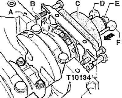
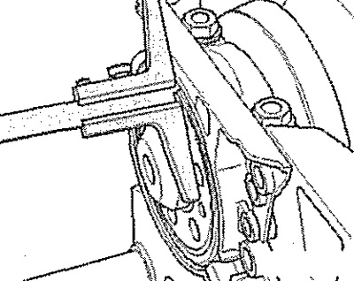
C. Screwing assembly tool -T10134- onto crankshaft flange
Slide the body of the assembly tool -C- by hand in the direction of the -arrow- until the support ring -B- rests against the crankshaft flange -A-. Insert guide pin for petrol engines (Red pen) -F- into the crankshaft hole. Thus, the master rotor will take up the mounting position.
Note: Never insert a guide pin for diesel engines into the threaded hole on the crankshaft (black pen) -D-.
Tighten both hexagon socket screws of the mounting tool. Screw nut -E- onto spindle until it rests on tool body -C-.
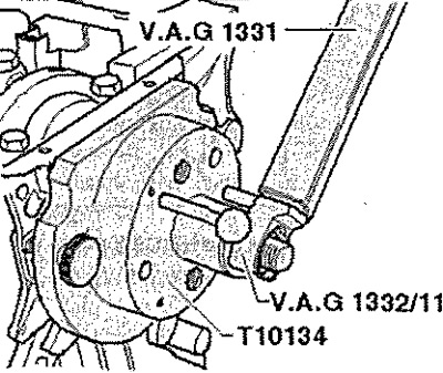
D. Pressing the input rotor onto the crankshaft flange using assembly tool -T10134-
Tighten nut of assembly tool -T10134- to 35 Nm. After tightening the nut to 35 Nm, there should still be a small gap between the cylinder block and the cover.
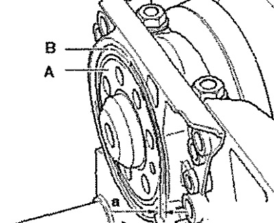
E. Checking the installation position of the driving rotor on the crankshaft
Loosen nut -E- to the end of the spindle. Remove both screws -A- from cylinder block. Remove knurled screws -B- from crankshaft cover. Remove assembly tool -T10134- from crankshaft flange by unscrewing hexagon socket head screws from crankshaft flange. Remove retaining ring.
Position depth gauge -VAS 6082- on crankshaft flange.
Measure protrusion -a- of crankshaft flange -A- in relation to drive rotor -B-. Rated value: Dimension -a- = 0.5 mm. If the nominal value is too low, repress the input rotor. If the set value is reached, carry out further installation.
F. Re-pressing the master rotor
Attach assembly tool -T10134- -pos. A - on the crankshaft flange, tightening the hexagon socket bolts by hand. Move special tool -T10134- to crankshaft cover by hand.
Screw nut -E- onto spindle until it rests on tool body -C-. Tighten nut of assembly tool -T1Q134- to 40 Nm. Check again the mounting position of the driving rotor on the crankshaft. If the nominal value is too low, tighten the nut of the mounting tool-T10134-to a torque of 45 Nm. Check again the installation position of the driving rotor on the crankshaft.
Assembly
Tighten the screws securing the crankshaft cover crosswise. Install oil pan. Install intermediate plate. Install flywheel.