



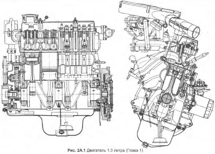
The engine is available in two versions: low or high compression. The low compression engine is marked with the code "135", and with high compression - code "136". Apart from the difference in compression ratio, which is achieved by using different pistons, both engines have the same design.
The cylinder block, cylinder head and valve cover are cast aluminum alloy. The walls of the cylinders are made in the form of cast-iron sleeves installed from below; sealing gaskets are installed at the base of each sleeve to prevent leakage of coolant into the sump.
The crankshaft has three main bearings. The clutch and flywheel are attached to a flange on the left end of the crankshaft. The double sprocket on the right end serves to drive the camshaft through a double row chain. Main and connecting rod bearings have liners.
At the right end of the camshaft there is a helical gear that drives the distributor. The camshaft also drives the oil pump via the distributor shaft.
The power-fed lubrication system consists of a gear pump that pumps oil from a sump through a strainer. Then the lubricant, passing through the filter installed on the cylinder block, is distributed to various engine components. On some models, an engine oil cooler may be used to maintain operating temperature during severe operating conditions.
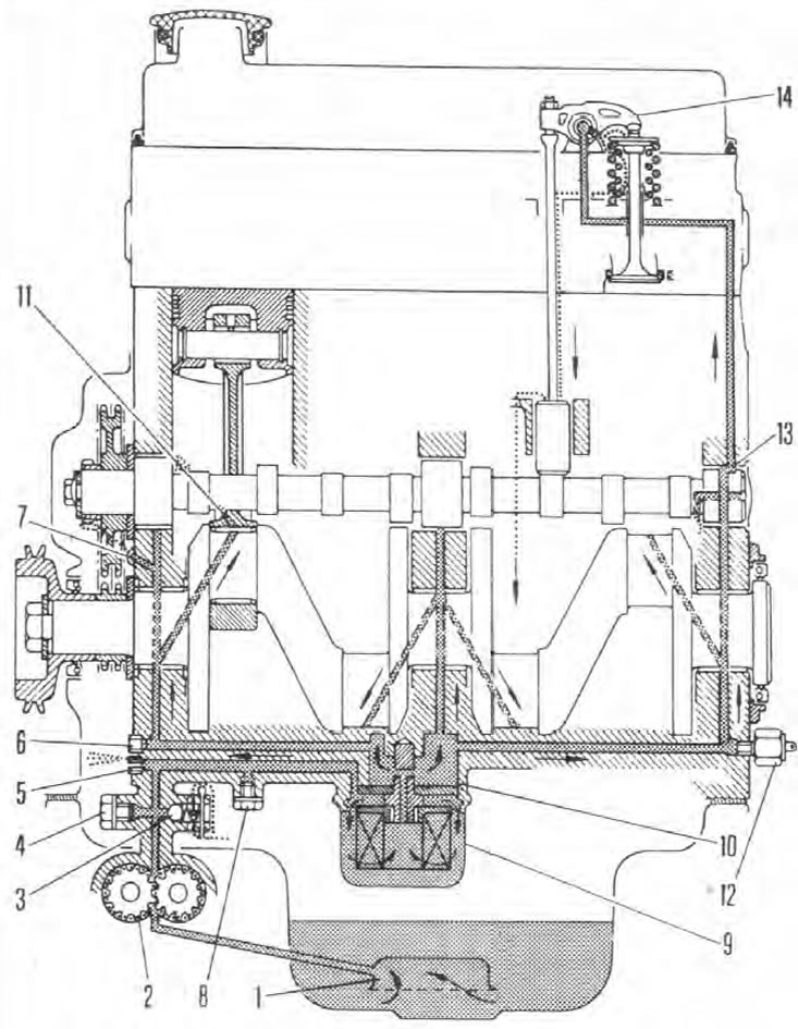
Pic. 2A.2. Engine lubrication system
1. Receiving tube strainer; 2. Oil pump; 3. Bypass valve; 4. Cork; 5. Jet (drive chain lubrication); 6. Cork; 7. Jet (distributor gear lubrication); 8. Cork; 9. Oil filter; 10. Bypass; 11. Oil jet connecting rod; 12. Oil pressure sensor; 13. Intermittent supply to the valve mechanism; 14. Valve mechanism.