



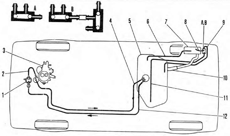
Pic. 4.1. Location of fuel system components
1. Fuel pump; 2. Hose; 3. Carburetor; 4. Fuel return hose; 5. Fuel tank; 6. Breather hose; 7. Filler neck of the fuel tank; 8. Ventilation hose; 9. Ventilation hose; 10. Filler hose; 11. Ventilation hose; 12. Fuel supply line; A. Splitter; B. Splitter (to the electronic control unit (EEC)).
The fuel system consists of a fuel tank installed under the bottom (in front of the rear axle), mechanical priming pump and carburetor (see fig. 4.1). The fuel priming pump is driven by an eccentric from the camshaft, and is mounted on the wall of the cylinder block. The air filter assembly contains a replaceable paper filter element. The temperature of the air intake is thermally controlled.
The models use a Pierburg 2ЕЗ or Jikov 28-30 LEKR carburetor, manufactured under license. In any case, they are identical. In order to reduce harmful emissions and improve overall cold handling performance, the intake manifold is heated by the coolant. The enrichment of the mixture for starting from a cold state is carried out by a temperature-controlled automatic air damper.
The exhaust system consists of three parts and is attached to the bottom of the car with rubber suspensions.
Warning: Many of the procedures in this Section require the removal of fuel lines and connections, which will usually result in some fuel leakage. Gasoline is extremely dangerous - use extreme caution when working on the fuel system.