
Steering column components
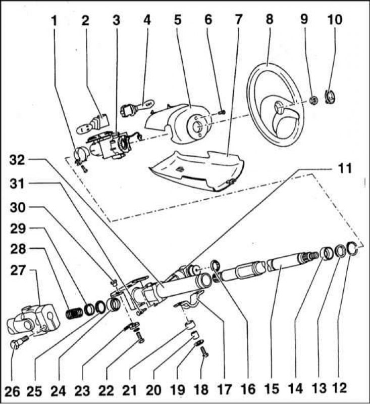
1 - Clamp; 2 - Assembling the steering column switches; 3 - Receiving nest; 4 - Lever of the steering column switch; 5 - Upper casing; 6 - Bolt; 7 - Lower casing; 8 - Steering wheel; 9 - Nut (35 Nm); 10 - Button for turning on the horn; 11 - Ignition lock / steering wheel lock; 12 - Retaining ring; 13 - Remote bushing; 14 - The upper bearing of the steering shaft; 15 - Steering shaft; 16 - Integumentary ring; 17 - Clamp; 18 - Bolt (25 Nm); 19 - Washer; 20 - Bushing; 21 - Rubber bushing; 22 - Bolt (25 Nm); 23 - Plastic compensation washer; 24 - The lower bearing of the steering shaft; 25 - Distance washer; 26 - Bolt (35 Nm); 27 - cardan intermediate shaft; 28 - Spring; 29 - Remote sleeve; 30 - Bushing; 31 - Shear head screw; 32 - Tubular casing of the steering column shaft
Note. On models equipped with a steering wheel collar, a puller will be required to remove it from the column.
Steering column - general information
The steering column shaft is made of steel. In order to ensure safety requirements, the column shaft is divided into two sections: the upper (steering column shaft) and bottom (cardan intermediate shaft).
Forks with universal joints installed in them are attached to both ends of the intermediate shaft. Hinge cages are made split and inside are provided with slotted connection.
The holder of the upper cardan joint is fixed on the lower spline connection of the steering column shaft. The holder of the intermediate shaft is fixed on the spline connection of the steering gear drive shaft. Each of the clips is tightened with an M8x30 bolt.
The steering column shaft passes through a hole in the bulkhead. Sealing is carried out by means of a rubber bushing.
The upper shaft of the column in the lower part ends with a cardan joint, and the upper one ends with slots and M14x1.5 thread. a steering wheel is seated on the upper trunnion of the shaft, which is then fastened with a nut. In addition to the wheel, an assembly of steering column switches is also installed in the upper part of the shaft.
A bracket with longitudinal cutouts is welded to the lower part of the tubular casing, through which two M8x22 bolts pass, with the help of which the pipe is attached to the shield in the front of the body. Approximately in the middle, the pipe is clamped with a clamp, which is attached to the engine compartment bulkhead with two M8x35 bolts.
Inside the tubular casing of the steering column shaft, two bearings of the PLC 03-33 type are installed, in which the steering column shaft rotates. Bearings are packed with grease at the factory and sealed, and therefore do not require additional maintenance.
A bracket is installed on the tubular casing, in which the ignition / steering lock is seated. The bolt of the lock enters the groove cut in the casing pipe. The bracket clip is clamped to the pipe using special bolts with shear heads (in order to prevent unauthorized disabling of the lock).
The steering wheel is mounted on the shaft by means of a M14x1.5 nut.
Overhaul
1. Remove the steering column (see Section Removal and installation of a steering column). Insert the key into the ignition switch and turn it to position 0.
2. Use paint or a marker to mark the position of the column shaft relative to the upper cardan joint of the intermediate shaft.
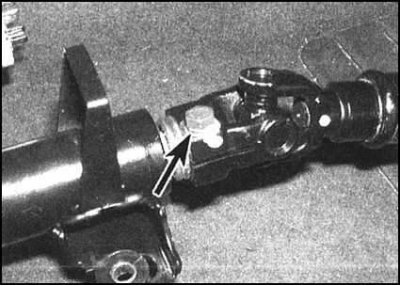
3. Turn out a coupling bolt and separate an intermediate shaft from a column.
4. Remembering the installation position of the components, remove the spring from the base of the column, then the remote and ring bushings. Remove the column shaft upward from the guide tube. Remove the lower support sleeve.
5. If equipped, a puller will be required to remove the steering wheel adapter from the top end of the column shaft.
6. Remove the circlip from the top end of the column shaft, then remove the spacer ring and top support sleeve.
7. Check the condition of the components, replace the defective ones.
8. When assembling, after installing the annular and support sleeves on the upper end of the shaft, immediately fix them with a retaining ring. Make sure the ring is seated correctly in its groove. Fit the steering wheel adapter onto the shaft if equipped.
9. Install the top bearing bushing into the guide tube, then carefully thread the shaft assembly into it. Put on the lower end of the shaft an annular and remote bushings and a spring.
10. Achieve the alignment of the marks applied during the dismantling process, then connect the intermediate shaft to the assembly. Make sure that the shaft fits correctly in the splines of the column, then tighten the coupling bolt with the required force.
11. Check that the speaker works properly, then install it on the car (see Section Removal and installation of a steering column).