
Steering gear assembly
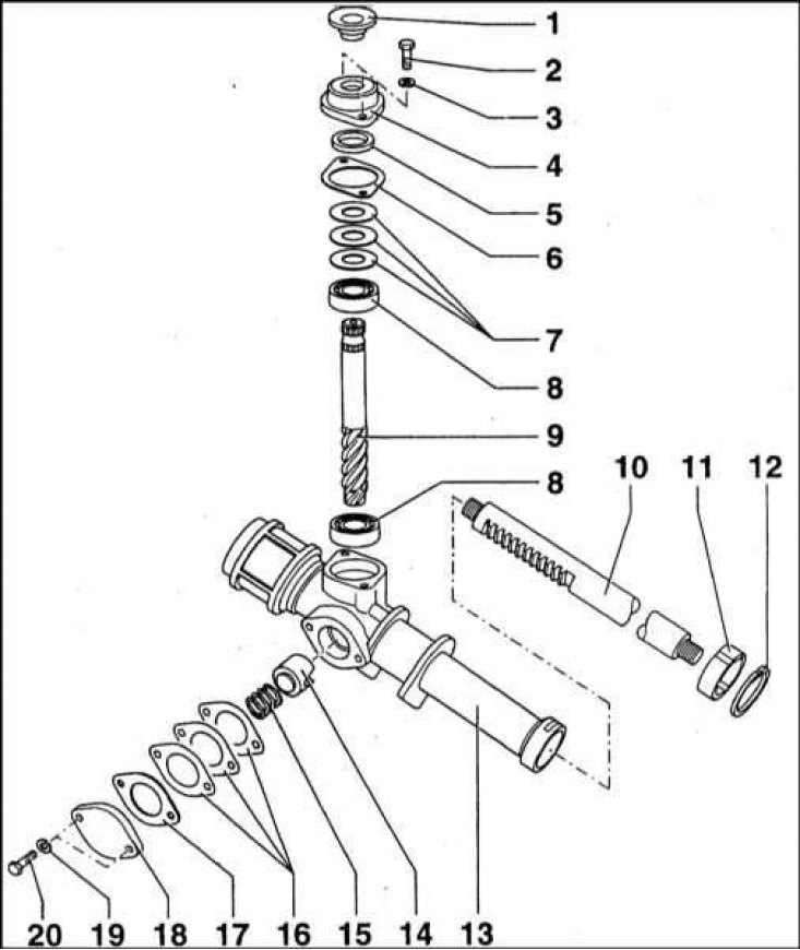
1 - Oil seal; 2 - Screw (7 Nm); 3 - Spring washer; 4 - Crankcase cover; 5 - O-ring; 6 - Sealing gasket; 7 - Adjusting washers; 8 - Ball bearing; 9 - Gear; 10 - Gear rack; 11 - Bushing; 12 - Retaining ring; 13 - Carter of the steering mechanism; 14 - Support washer; 15 - Spring; 16 - Adjusting shims; 17 - Sealing gasket; 18 - Cover; 19 - Spring washer; 20 - Bolt (7 Nm)
Steering gear housing
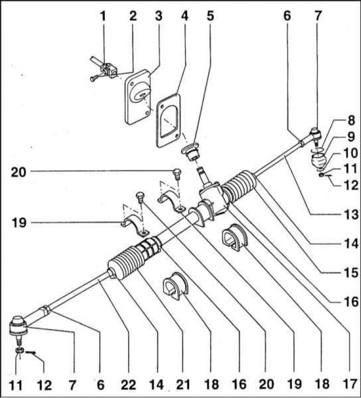
1 - Cardan intermediate shaft of the steering rack; 2 - Bolt (5 Nm); 3 - Protective sheet; 4 - Sealing gasket; 5 - Oil seal; 6 - Nut (60 Nm); 7 - Tie rod end; 8 - Retaining ring; 9 - Protective cover of the ball joint; 10 - Ring; 11 - Castellated nut; 12 - Cotter pin; 13 - Left tie rod; 14 - Clamp; 15 - Protective cover; 16 - Connecting link; 17 - Carter of the steering mechanism; 18 - Rubber cushion; 19 - Clamp rubber cushion; 20 - Bolt (25 Nm); 22 - Right steering rod
Location of power steering components
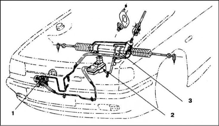
1 - Steering pump; 2 - Reservoir; 3 - Steering gear with distributor and power cylinder
Steering gear with hydraulic booster
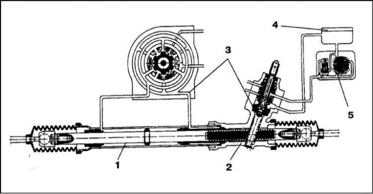
1 - Power cylinder; 2 - rack and pinion; 3 - Distributor valve; 4 - Reservoir; 5 - Steering pump
Vane steering pump
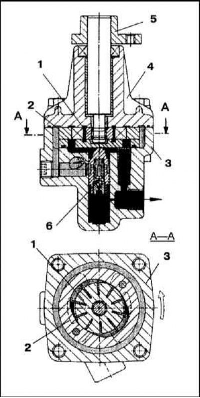
1 - Rotor; 2 - Stator; 3 - Housing; 4 - Cover; 5 - Pulley flange; 6 - Safety valve
General information
Models without power steering
The rack and pinion converts the rotation of the steering column into the movement of rods that turn the steered wheels of the car.
The steering box is made of aluminum alloy. The transmission consists of a drive shaft-gear and a gear rack.
The steering drive shaft is equipped with a gear and mounted in the rack and pinion housing in two PLC 03-29/1 bearings. The shaft assembly is in constant engagement with the gear rack rigidly connected to the steering rods. The rotation of the shaft causes the rack to move to the right or left. Together with the rack, the steering rods also move, forcing the front wheels of the car to turn.
The crankcase of the steering mechanism is closed from above by a cover fixed with two M6x20 bolts. The cover is installed on the sealing gasket. A hole is provided in the middle of the crankcase through which the steering gear drive shaft passes. In order to seal the assembly, an oil seal 17x28x7 is installed in the hole.
In order to select the backlash of the shaft bearings, shims with a thickness of 0.1 and 0.2 mm are used.
The side opening in the crankcase is also closed with a cover, which is fastened with two M6x20 bolts. A sealing gasket is installed under the cover. A bolt passes through the hole in the middle of the cover, designed to adjust the gap in the engagement of the shaft with the gear rack. The position of the bolt is fixed with a locknut. The required gap in engagement is maintained by a spring-loaded cracker and equipped with a 28x20 O-ring.
The right side of the crankcase of the steering mechanism is a pipe, inside of which a bushing is planted. A gear rack is placed in the sleeve. The ends of the rack are connected to the steering rods.
Rubber protective covers protect the steering mechanism from contamination, and also prevent the leakage of grease, which is filled in the crankcase.
The steering gear is attached to the bracket by the cross member of the front suspension beam on two rubber bearings, which are installed in clips. Each of the clips is fastened with two M8x20 bolts. Both supports and clips are different from each other (larger components are mounted closer to the steering gear).
Models with power steering
Power steering components are manufactured by TRW Dusseldorf.
The system consists of a rack and pinion steering mechanism, combined in one housing with a power cylinder and a control valve, a steering pump, a hydraulic fluid reservoir and connecting hydraulic lines.
Tie rods are somewhat shorter than those used on models with manual steering. full steering wheel travel (from end to end) is 3.0 turns (vs. 3.6 turns in manual models). The decrease in the number of shaft revolutions is associated with a lower gear ratio of the rack and pinion mechanism.
Note. In view of the foregoing, in the event of a failure of the hydraulic booster system, the steering continues to work, however, it requires great effort when making turns.
When the engine is running, hydraulic fluid is supplied by the steering pump to the rack and pinion control valve. At the start of the steering wheel turn (before moving the rail) the valve-distributor rotates and the liquid is directed to the corresponding cavity of the power cylinder. As long as the driver applies force to the steering wheel, the control valve is displaced and fluid continues to flow into the cylinder. As soon as the rotation of the wheel stops, the control valve is shifted to the middle position and the fluid supply to the cylinder is stopped (the pressure line is connected to the return). At the same time, the pump continues to operate in idle mode, freely pumping liquid through the valve. Thus, the hydraulic booster constantly remains ready to work. If the driver, having turned the steering wheel to the stop, continues to apply force to it in the extreme position, the control valve remains in the displaced position and fluid pressure continues to act on the cylinder piston. At the same time, the maximum performance of the pump develops and intensive heating of the liquid occurs as a result of an increase in its pressure. In view of the foregoing, you should not hold the steering wheel in its extreme position for too long, risking damaging the device. The degree of amplification depends on the amount of effort applied to the steering wheel - the harder the driver presses on the steering wheel, the more the control valve is displaced, increasing the fluid flow and the power developed by the amplifier.
When the wheel hits an obstacle (e.g. curb or stone), the control valve tends to move to the middle position, the fluid pressure decreases, and the effort on the steering gear increases. The driver strives to keep the wheels in the right position; in this case, the distribution valve is displaced from the middle position and directs the fluid flow into the corresponding cavity of the cylinder, preventing the rail from moving. Thus, feedback is provided from the wheels to the driver.
The working path of the hydraulic booster system is filled with a special Pentosin CHF 11 S fluid in the amount of 0.9 l, which simultaneously acts as a lubricant for the components of the steering mechanism and pump. Hydraulic lines laid between the pump, control valve, power cylinder and hydraulic fluid reservoir are made of metal tubes and rubber hoses. Each section is equipped with special fitting tips.
The main working element of the system is the vane steering pump. The rotor with movable plates rotates in a specially shaped stator. When the pump is running, the liquid enters from the rarefaction side, enters the chamber formed by the rotor plates and the stator walls. The volume of the chamber gradually decreases as the rotor turns, the pressure of the liquid increases and it begins to be pushed out through the connecting line into the distribution valve. When the maximum allowable pressure is exceeded, a safety valve is activated that connects the working cavity with the rarefaction chamber. The pressure then drops abruptly. The maximum performance of the pump is achieved at a rotor speed of 500 to 700 rpm. The maximum pressure developed by the pump is 20 kPa. The pump is driven by a multi-ribbed belt, which is also used in parallel to drive the A/C compressor, generator and pump.
The power cylinder, combined with the steering mechanism and the control valve, is attached to the suspension cross beam with M10x1.25 bolts (in contrast to the M8 bolts in the case of a manual steering mechanism).
The power steering is equipped with diesel models and petrol models of 1.6 liters. The difference lies only in the route of laying the connecting lines.
Removing
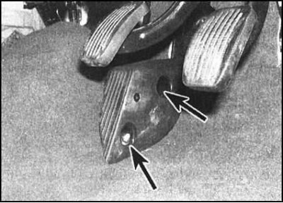
1. In the car, give the fixing nuts and remove the foot rest assembly from the clutch pedal.
2. With the appropriate configuration, fold back the carpet, give the screw and nut of the trim casing of the steering column base. Remove the casing to provide access to the lower cardan joint of the intermediate shaft.
3. Use paint or marker to mark the position of the pivot in relation to the rack and pinion drive gear, then remove the pivot assembly pinch bolt.
4. Give the nuts, remove the washers and release the sealing plate and gasket installed around the drive gear.
Note. A damaged gasket must be replaced.
5. Firmly apply the parking brake, then jack up the front of the vehicle and place it on jack stands. Remove both front wheels.
6. Remove the cotter pins, then give the nuts securing the tie rod ends to the hub assemblies. Release the tips from the pivot arms of the hubs - if necessary, use a ball joint puller.
Models without power steering
1. Turn out fixing bolts and remove collars of fastening of the steering mechanism from a stretcher.
2. Separate the rack and pinion assembly from the intermediate shaft and remove it from under the vehicle. Remove the rubber pads from the steering gear (cushions are not interchangeable). Remove the sealing plate with gasket from the car interior.
Models with power steering
1. In order to minimize the loss of hydraulic fluid, use special clamps or clamps to pinch the supply and return hoses near the steering pump reservoir.
2. Having marked the connectors, unscrew the nipple bolts on the steering gear assembly (prepare a drain container to collect the leaking hydraulic fluid). Disconnect both hoses and remove sealing washers.
Note. During assembly, the sealing washers must be replaced without fail. Seal open hose ends and steering case openings immediately to minimize hydraulic fluid loss and prevent dirt from entering the system.
3. Release hydraulic hoses from intermediate clamps and take them aside from assembly of the steering mechanism.
4. Turn out fixing bolts and remove collars of fastening of rack assembly from a stretcher.
5. Separate the rack and pinion assembly from the intermediate shaft and remove it from under the vehicle. Remove the rubber pads from the steering gear (cushions are not interchangeable). Remove the sealing plate with gasket from the car interior.
Overhaul
1. Steering rack and pinion is one of the very reliable components of the car. The failure-free operation of the mechanism depends on the quality of the lubrication of internal components, the condition of the protective covers, the proper balance of the wheel assemblies, and the amount of play in the steering gear.
2. A distinctive feature of the rack and pinion steering mechanism is that any vibration and jerks associated with wheel imbalance, road surface irregularities and weakening of the wheel bearing preload are inevitably transmitted directly to the steering wheel.
3. In order to perform a major overhaul, the steering gear assembly must be removed from the vehicle.
4. After dismantling the assembly, the oil level in it can be easily replaced or adjusted. The oil is drained through by removing the rubber protective covers from the crankcase flanges, for which you must first remove the mounting clamps.
5. With the larger rubber boot in place, position the steering gear housing vertically and fill it with the required amount of oil of the required grade through the end where the shorter boot fits. Install the second cover on the crankcase and secure it with a clamp. Move the crankcase to a horizontal position and check it for signs of leakage from under the protective covers. Tighten the clamps if necessary.
6. When replacing rubber protective covers, it is necessary to unscrew the tie rod ends and drain the oil from the crankcase. Now the covers can be removed and replaced with new ones. Then fill the crankcase with fresh oil, fasten the clamps and reinstall the tie rod ends.
7. Disassembly of the steering mechanism in order to perform a refurbishment or replacement of failed internal components is carried out as follows:
- a) Remove the clamps of the rubber covers;
- b) Bend the edges of the covers and drain the oil from the crankcase into a clean container;
- c) Slide the covers towards the tie rod ends;
- d) Bend back the flags of the flat lock washers locking the nuts at the ends of the gear rack;
- e) Using a screwdriver, bend the recess on the edge of the adapter sleeve in the rail groove;
- f) Give nuts and disconnect from a lath of draft;
- g) Unscrew the two bolts securing the side cover to the crankcase, remove the spring, cracker and rubber sealing ring;
- h) Remove the steering gear shaft with the upper bearing from the crankcase (clamp the shaft in a vice with soft jaws and pull the crankcase; use a soft-faced hammer if necessary);
- i) Using a puller, remove the bearing from the shaft;
- j) Remove the gear rack from the crankcase of the steering mechanism;
- k) Using the special tool, remove the lower bearing from the crankcase.
8. After replacing the defective components, assemble the mechanism:
- a) Install the lower shaft bearing in the crankcase;
- b) Lubricate the rack with gear oil and fill it into the steering gear housing with the smooth side to the side hole;
- c) Insert the shaft into the crankcase with the upper bearing mounted on it and plant the assembly with hammer blows so that the lower bearing is also on the shaft (make sure that the upper bearing does not have any movement towards the teeth of the shaft);
- d) Lubricate the edges of the hole from which the shaft protrudes with a small amount of gear oil, lay the sealing gasket of the top cover on the mating surface;
- e) Measure the distance between the outer race of the bearing and the top surface of the gasket;
- f) Select shims so that their thickness corresponds to the measured distance, plus 0.1 mm (washers are available in thicknesses of 0.1 and 0.2 mm);
- g) Install washers (first adjustable, then normal), lubricate the cover with a small amount of gear oil, install it on the assembly and tighten the fixing bolts (pre-lubricate the threads of the bolts with sealant);
- h) Tighten the bolts to the required torque (7 Nm);
- i) Check the freedom of rotation of the shaft, evaluate the backlash of the assembly components;
- j) Lubricate the inner surface of the side hole in the steering gear housing with gear oil;
- k) Insert the toothed rack cracker, rubber sealing ring and spring into the hole;
- l) Lubricate the mating surfaces of the bore and cover with gear oil;
- m) Install the sealing washer and tighten the two mounting bolts to the correct torque (7 Nm);
- n) Estimate the backlash of the mechanism, if necessary, make an appropriate adjustment;
- o) Screw new adapter bushings onto both ends of the rail and tighten them to the required torque (50÷60 Nm). To tighten the bushings, screw on the lock nuts and special nuts. Clamp one pair of nuts in a vise, tighten the second with the required force and lock with a lock nut. Now clamp the already tightened nut in a vise (together with counter) and repeat the procedure with the opposite sleeve;
- p) Lock the bushings by flaring their edges into the grooves on the rail;
- q) Insert a plate inside each of the bushings;
- r) Screw a special nut onto the steering rod with a flat surface to the tip of the rod;
- s) Lubricate the rod end;
- t) Install the lock washer on the reduction sleeve;
- u) Screw a special nut on the thread of the reducing sleeve, which is put on the steering rod. Tighten the nut so that a force of 12.5 ÷ 20.5 Nm is required to deflect the rod. Tighten the lock nut with a force of 50 ÷ 60 Nm and block it with a lock washer, bend the flag of the latter onto the slot of the nut and lock nut;
- v) Proceeding in a similar manner, secure the opposite thrust;
- w) Install protective covers on the rods and secure them with clamps;
- x) Pull the longer cover over the crankcase flange and secure it with a clamp;
- y) Fill the crankcase with fresh oil, then install the assembly on the vehicle.
Installation
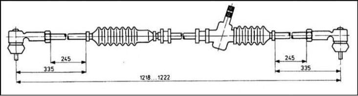
1. Install the rubber pads on the steering gear with the flat side down. When installing it is necessary to observe the dimensions shown in the illustration.
2. Thoroughly clean the mating surfaces and install the sealing plate and gasket on the inside of the bulkhead of the engine compartment.
3. Install the steering gear assembly on your regular one, being careful not to damage the sealing plate of the bulkhead. With the help of an assistant, achieve alignment of the landing marks made during dismantling and engage the intermediate shaft with the splines of the rack and pinion drive gear.
4. Make sure the rubber pads on both mounts are flat-sided against the subframe, then install the mounting clips.
5. Clean the threads of both mounting bolts, then lightly lubricate them with Loctite 270 locking compound. Screw in the bolts and tighten them evenly in several stages to the required torque.
6. In the passenger compartment, make sure that the sealing plate is properly seated relative to the steering gear housing, then firmly tighten the fixing nuts.
7. Make sure that the universal joint of the intermediate shaft is installed correctly, then screw in the coupling bolt of the hinged assembly and tighten it with the required force. Reinstall the column base trim if supplied.
8. Insert the tie rod ends into the pivot arms of the hub assemblies. Screw on the fixing nuts, tighten them firmly and secure with new cotter pins.
9. Replace the wheels, then lower the vehicle to the ground and tighten the wheel bolts to specification.
10. In conclusion, check the angles of the front wheels, if necessary, make the appropriate adjustment (see Section Vehicle wheel alignment - general information).
Models with power steering
1. Follow the procedures in the Removal subsection.
2. Install new sealing washers on both sides of the hydraulic hose nipple connections, then screw in the nipple bolts and tighten them to the required torque without removing the clamps/clamps from the hoses.
3. Replace the wheels, then lower the vehicle to the ground and tighten the wheel bolts to the correct torque.
4. Add fresh hydraulic fluid to the steering pump reservoir (see Section Removal of air pockets from the hydraulic path of the power steering system).
5. Finally, check the angles of the front wheels, if necessary, make the appropriate adjustment (see Section Vehicle wheel alignment - general information).