



Valve clearance adjustment
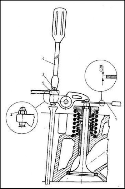
1 - Measuring probe; 2 - Lock nut; 3 - Adjusting screw; 4 - Screwdriver; 5 - Key
Note: The valve lifters of 1.6L engines are equipped with hydraulic compensators, so there is no need to adjust the valve clearances.
1. The efficiency of the engine largely depends on the correct adjustment of valve clearances. Exceeding the permissible value of valve clearances leads to a delay in the operation of the valves (opening too late and closing too early). On the other hand, too tight a fit of components is fraught with the risk of loss of compression pressure as a result of incomplete valve closure due to thermal expansion of the pushrods. In addition, in such a situation, intensive burning of the valve plates and seats occurs.
2. Adjust the valve clearances on a cold engine (the clearances of the intake and exhaust valves at an engine temperature of +20°C should be 0.20 mm). If the intake valve stems are made of aluminum rather than steel, the clearance should be set to 0.25 mm. Remove the cylinder head cover (see Chapter Engine repair). In order to make it easier to turn the crankshaft, it makes sense to also remove the spark plugs (see section Replacing Spark Plugs - 1.3L Models).
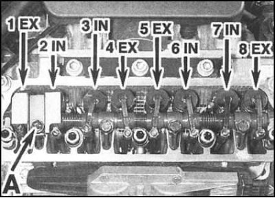
3. In order to provide access to the first two valves, unscrew the mounting bolt and remove the oil deflector A installed under the engine oil filler cap.
4. The tappet of the valve to be adjusted must rest against the heel of the corresponding camshaft cam (achieved by turning the crankshaft). For convenience, the valves are numbered starting from the one closest to the timing chain. Adjustment is made in accordance with this numbering, which allows avoiding unnecessary crankshaft rotations. Below is a table that is convenient for determining the order of adjustments:
Valve No.8 | Valve No.1 | (Issue) |
| Valve No.6 | Valve No.3 | (Inlet) |
| Valve No.4 | Valve No.5 | (Issue) |
| Valve No.7 | Valve No.2 | (Inlet) |
| Valve No.1 | Valve No.8 | (Issue) |
| Valve No.3 | Valve No.6 | (Inlet) |
| Valve No.5 | Valve No.4 | (Issue) |
| Valve No.2 | Valve No.7 | (Inlet) |
5. The required valve clearance dimensions are given in the Specifications. To perform the adjustment, loosen the hexagonal lock nut of the rocker arm spherical support with a wrench. The support is held from turning with a screwdriver.
6. Insert the blade of the feeler gauge of the thickness specification into the gap between the end of the valve stem and the working surface of the rocker arm. Rotate the adjusting screw of the spherical support until the blade fits tightly in the gap. After fixing the support in the required position, tighten the lock nut and repeat the check.
7. While turning the crankshaft accordingly, repeat the procedure for the remaining valves in the order specified above.
8. Install the oil deflector and tighten the mounting bolt to the required torque. Replace the cylinder head cover and (if you filmed) spark plugs (see section Replacing Spark Plugs - 1.3L Models).