



Engine 1.3 l
Checking the working clearances of bearings
1. When installing a machined crankshaft complete with original liners manufactured by Skoda, the need for the checks described below disappears.
2. Checking the working clearance in the connecting rod bearings should be done if there is the slightest doubt when assessing the degree of wear of the connecting rod journals of the shaft, as well as after turning the shaft and equipping it with non-branded liners. Checking can be done by one of two methods.
3. The first method gives less accurate results and requires bolting the caps to the lower heads of the connecting rods that are not mounted on the shaft journals (the inserts must be placed in their own beds). Secure the connecting rod lower head caps with old nuts, tightening them to the required torque. Next, using a bore gauge or a Columbus equipped with a vernier scale, measure the internal diameters of the assembled bearings. The diameter of the corresponding crankshaft journal is then subtracted from the result obtained for each assembly.
(The original article is available on Skodabook.ru)
4. The second method is based on the use of calibrated wire from the Plastigauge set (see section Installing the crankshaft and checking the main bearing clearances). All components must be thoroughly wiped and installed without lubrication.
5. Place the corresponding lengths of plastic wire from the measuring kit along the crank journals in the BDC positions. Place the connecting rods on the journals, install the connecting rod bearing caps in place and tighten the nuts/bolts securing them with the required force. Try not to shift the calibrated wire pieces placed on the shaft journals.
6. Without turning the connecting rods, remove the caps and determine the working clearances of the bearings by the degree of flattening of the wire. The thickness of the flattened wire is measured using the scale printed on the packaging of the Plastigage kit. Compare the measurement results with the requirements Specifications. If the measurement results differ from those specified in Specifications, you should check whether the installed liners are correctly sized. Also make sure that no foreign particles have gotten between the backs of the liners and the bearing beds. Measure the diameters of the crankshaft journals again. If the width of the flattened section of calibrated wire at one end is greater than at the opposite end, you should check the corresponding journal of the shaft for excessive taper. If necessary, replace the liners or regrind the shaft with new liners of the appropriate repair size (with disparagement). Finally, carefully scrape any traces of flattened wire from the journals of the shaft with the edge of an old credit card. Rotate the shaft, bringing the pistons of the second and third cylinders to the BDC positions, and repeat the check for the remaining bearings.
Final installation of connecting rod and piston groups
1. Before starting the procedure, make sure that the liners are correctly seated in the cylinders of the block and that they are securely fixed with special rectangular washers (see section Cleaning and checking the condition of the cylinder block/engine crankcase). The crankshaft and main bearing caps must be finally installed on the engine.
2. Wipe the backs of the bearings and insert them into their beds in the lower heads of the connecting rods and their caps. When installing new bearings, make sure that all traces of preservative grease are removed from them - use kerosene or another suitable solvent to wipe the bearings. Wipe dry the clean bearings with a lint-free rag. Wipe the connecting rods with the same rag.
3. Tightly seat the liners in the beds, making sure that the guide tabs fit into the corresponding grooves in the connecting rods and connecting rod caps. Try not to touch the working surface of the liners. Old liners suitable for further use must be installed strictly in their previous positions.
4. Lubricate the cylinder bores, pistons and piston rings with clean engine oil. Lay the connecting rod and piston assemblies on a clean work surface in the order in which they are installed on the engine.
5. Begin by installing the connecting rod and piston assembly of the first cylinder. Make sure that the piston ring joints are still at the correct angles to each other (see section Installing piston rings). Press the rings with a special tool mandrel.
6. Insert the corresponding assembly into the first cylinder of the engine through the top with the connecting rod first. Take care not to accidentally scratch the cylinder wall. Make sure that the arrow mark on the piston bottom is directed towards the location of the timing drive. Note that the connecting rod should also be turned with the oil flow forward along the engine.
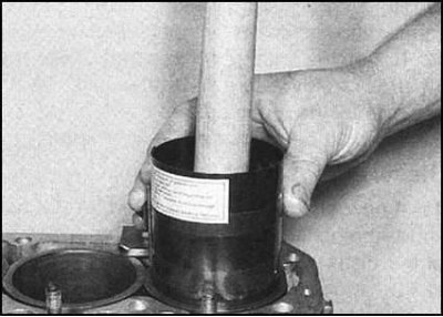
7. Using the wooden handle of a hammer against the piston crown, push its skirt into the cylinder, pressing the ring-pressing mandrel of the tool firmly against the surface of the block. Continuing to press the mandrel firmly, push the piston further until its crown is flush with the surface of the cylinder block mating with the head.
8. Make sure that the connecting rod bearing shells are seated correctly in their beds. Generously lubricate the journal of the first crankshaft crankshaft with clean engine oil. Lubricate both shells with the same oil.
9. Taking care not to damage the cylinder bore, carefully place the lower connecting rod head onto the crankshaft journal brought to the BDC position.
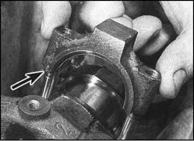
10. Install the connecting rod bearing cap, making sure that the seat marks are aligned correctly.
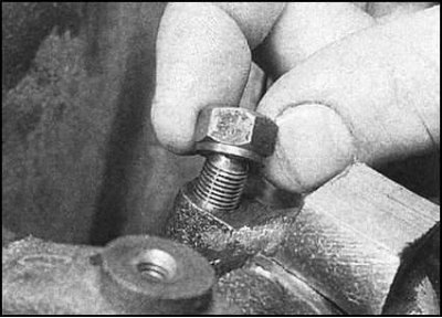
11. Screw on the fastening nuts (with the rim to the lid) and tighten them evenly in several stages to the required force. Check the freedom of rotation of the crankshaft, then proceed to install the next assembly.
 |
 |
12. Proceeding in a similar manner, install all remaining connecting rod and piston assemblies onto the engine.
13. Check the freedom of rotation of the shaft. The presence of slight resistance is quite natural and is explained by the unworked-in state of the new components, however, the presence of obvious jerks and jamming points is in no way acceptable.
1.6L and diesel engines
Checking the working clearances of bearings
Note: This assumes that the crankshaft is already installed in the engine (see section Installing the crankshaft and checking the main bearing clearances).
1. As in the main bearings, the connecting rod bearings must have a strictly defined working clearance, ensuring effective lubrication of the rubbing sliding surfaces.
2. Place the cylinder block on the workbench with the crankcase facing up. Bring the cranks of the first and fourth cylinders to the BDC positions. Determining the size of the working clearances in the bearings can be done by one of two methods.
3. The first method gives less accurate results and requires bolting the caps to the lower heads of the connecting rods that are not mounted on the shaft journals (the inserts must be placed in their own beds).
Note: It is extremely important that the lids are oriented correctly (see section Removal, condition check and installation of connecting rod and piston assemblies). Secure the connecting rod lower head caps with old bolts/nuts, tightening them to the required torque. Next, using a bore gauge or a Columbus equipped with a vernier scale, measure the internal diameters of the assembled bearings. The diameter of the corresponding crankshaft journal is then subtracted from the result obtained for each assembly.
4. The second method is based on the use of calibrated wire from the Plastigauge set (see section Installing the crankshaft and checking the main bearing clearances). All components must be thoroughly wiped and installed without lubrication.
5. Place the appropriate lengths of plastic wire from the measuring kit along the crankpins in the BDC positions. Make sure that the liners are seated correctly in their beds, then put the connecting rods on the journals, install the connecting rod bearing caps in place (make sure the markings are aligned correctly)
6. Tighten the nuts/bolts of their fastening with the force of the first stage. Try not to shift the pieces of calibrated wire laid on the journals of the shaft.
7. Without turning the connecting rods, remove the caps and determine the working clearances of the bearings by the degree of flattening of the wire. The thickness of the flattened wire is measured using the scale printed on the packaging of the Plastigage kit. Compare the measurement results with the requirements Specifications.
8. If the measurement results differ significantly from those specified in Specifications, you should check whether the installed liners are correctly sized. Also make sure that no foreign particles have gotten between the backs of the liners and the bearing beds. Measure the diameters of the crankshaft journals again. If the width of the flattened section of calibrated wire at one end is greater than at the opposite end, you should check the corresponding journal of the shaft for excessive taper. If necessary, replace the liners or regrind the shaft with a selection of new liners of the appropriate repair size (with disparagement).
9. Finally, carefully scrape any traces of flattened wire from the journals of the shaft with the edge of an old credit card. Turn the shaft, bringing the pistons of the second and third cylinders to the BDC positions and repeat the check for the remaining bearings.
Checking the preload of the connecting rod bearing shells on 1.6 l engines
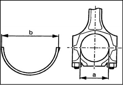
10. Using a Columbus equipped with a vernier scale, measure the inside diameter of the assembled lower connecting rod heads. Then measure the outside diameter of the bearings. Subtract the results of the second calculation from the results of the first calculation - the resulting value determines the preload of the bearings and should not be lower than that specified in Specifications values. Otherwise, the liners must be replaced.
Final installation of connecting rod and piston groups
1. The crankshaft and main bearing caps must be installed on the engine (see section Installing the crankshaft and checking the main bearing clearances).
2. Make sure the bearings are seated correctly in their beds. When installing new bearings, make sure that all traces of preservative grease are removed from them - use kerosene or another suitable solvent to wipe the bearings. Wipe the clean bearings dry with a lint-free cloth. Wipe the connecting rods with the same cloth.
3. Tightly seat the liners in the beds, making sure that the guide tabs fit into the corresponding grooves in the connecting rods and connecting rod caps. Try not to touch the working surface of the liners. Old liners suitable for further use must be installed strictly in their previous positions.
4. Lubricate the cylinder bores, pistons and piston rings with clean engine oil. Lay the connecting rod and piston assemblies on a clean work surface in the order in which they are installed on the engine.
5. Begin by installing the connecting rod and piston assembly of the first cylinder. Make sure that the piston ring joints are still at the correct angles to each other (see section Installing piston rings). Press the rings with a special tool mandrel.
6. Insert the corresponding assembly into the first cylinder of the engine through the top with the connecting rod first. Take care not to accidentally scratch the cylinder wall. Make sure that the arrow mark on the piston bottom is directed towards the location of the timing drive. Note that the connecting rod should also be turned with the oil flow forward along the engine.
7. Using the wooden handle of a hammer against the piston crown, push its skirt into the cylinder, pressing the ring-pressing mandrel of the tool firmly against the surface of the block. Continuing to press the mandrel firmly, push the piston further until its crown is flush with the surface of the cylinder block mating with the head.
8. Make sure that the connecting rod bearing shells are seated correctly in their beds. Generously lubricate the journal of the first crankshaft crankshaft with clean engine oil. Lubricate both shells with the same oil.
9. Taking care not to damage the cylinder bore, carefully place the lower connecting rod head onto the crankshaft journal brought to the BDC position.
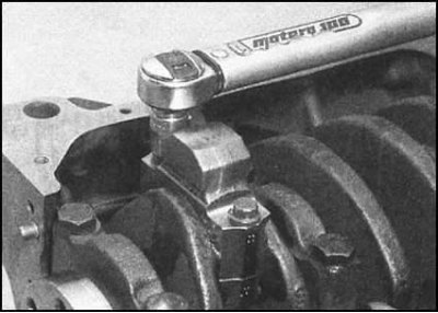
10. Install the connecting rod bearing cap, making sure that the seat marks are aligned correctly.
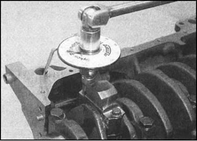
11. Screw on the fastening nuts (with the rim to the lid) and tighten them evenly in several stages to the required force. Check the freedom of rotation of the crankshaft, then proceed to install the next assembly.
12. Proceeding in a similar manner, install all remaining connecting rod and piston assemblies onto the engine.
13. Check the freedom of rotation of the shaft. The presence of slight resistance is quite natural and is explained by the unworked-in state of the new components, however, the presence of obvious jerks and jamming points is in no way acceptable.
Diesel engines
1. When installing new pistons or a new shortened block, the height of the pistons protruding to the TDC position above the cylinder head should be checked in order to select the required head gasket.
2. Turn the block upside down and place it on wooden blocks. Attach a plunger-type dial gauge to the block, zero it, and press the plunger against the bottom of the No.1 piston. Slowly rotate the crankshaft by hand until the piston passes TDC. Record the reading.
3. Repeat the procedure by measuring the piston protrusion of the 4th cylinder, then turn the shaft 180° and take measurements for the pistons of the 2nd and 3rd cylinders.
4. If the measurement results differ from each other, the maximum reading should be taken as the reference. Compare the result with the requirements Specifications.
5. When installing old pistons that are suitable for further use, you should select a gasket that is equal in thickness to the old one removed from the engine.