
Typical examples of crankshaft bearing shell wear
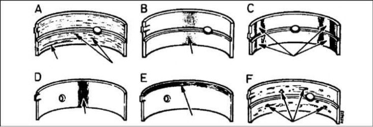
A - Scratched by foreign particles - grains are visible, immersed in the working layer of the liner; B - Lack of oil - the top layer is worn off; C - The earbuds are incorrectly positioned during installation - there are shiny (polished) plots; D - The neck is reduced to a cone - the top layer is removed from the entire surface; E - Wear of the edge of the liner; F - Fault "fatigue" - craters or pockets formed
Examination
1. Despite the obligation to replace the liners of the main and connecting rod bearings during the overhaul of the engine, the condition of the old liners must be subjected to the most careful study, since a lot of useful information about the general condition of the engine can be gleaned from the results of such an analysis.
2. Bearing failure can occur as a result of lack of lubrication, ingress of dirt or foreign particles, motor overload, corrosion development, and other adverse effects. Regardless of the nature of the defect, the cause of its occurrence must be identified and eliminated before the engine is assembled in order to avoid recurrences.
3. For inspection, remove the liners from their beds in the cylinder block / crankcase, main and connecting rod caps and lower connecting rod heads. Lay the removed liners on a clean, level work surface in the order in which they are placed on the engine so that they match the condition of the corresponding crankshaft journals.
4. Dirt and foreign particles enter the engine in various ways. They can be left inside after an overhaul is completed, as a result of careless cleaning procedures, or they can get through filters or the crankcase ventilation system. Often, dirt first enters the engine oil and already with it penetrates into the bearings. It should not be forgotten that metal filings are inevitably formed during the normal wear of the engine. If, after performing restoration work, due attention is not paid to the engine cleaning procedure, abrasive particles will certainly remain in it. Regardless of the method of penetration into the engine, all foreign particles sooner or later find themselves embedded in the soft surface of the working layer of the plain bearing shells and are easily recognized by visual inspection of the latter. The largest particles usually do not get stuck tightly in the liners, but leave deep grooves and scuffs on their working surfaces and the surfaces of the corresponding shaft journals. The best prevention of this kind of defects is to conscientiously clean the engine after the overhaul is completed and install only absolutely clean components during assembly. Also, do not forget the need to perform a regular and frequent change of impellent oil.
5. Oil starvation can also be caused by several reasons, often closely related to each other. These include engine overheating (leading to oil dilution), overload (as a result of which the oil is forced out of the bearings), oil leak (associated with excessive running clearance in the bearings, wear of the oil pump, or excessive increase in engine speed) and so on. Oil flow problems, most often associated with careless installation of components during assembly, leading to misalignment of the oil holes, also cause a reduction in the oil supply to the bearings and, ultimately, the failure of the liners. A characteristic sign of oil starvation is the wiping and displacement of the soft working layer of the liners from the steel substrate. Sometimes the temperature rises to such an extent that purple spots form on the substrate.
6. It should be remembered that the driving style also has a significant impact on the service life of the bearings. An increase in the load on the engine is facilitated by frequent full opening of the throttle valve, movement at low speeds, etc. As a result, the oil film is forced out of the working clearance of the bearings, which leads to softening of the bearing shells and the formation of small cracks on their working surface (fatigue strain). Ultimately, individual fragments of the material of the working layer come off and fall out of the substrate.
7. The operation of a car in an urban cycle is often associated with making many short trips, which leads to the development of corrosion of the bearings, since insufficient warming up of the engine contributes to the formation of condensate inside it and the formation of chemically aggressive gaseous mixtures. Aggressive products accumulate in the engine oil, forming sludge and acid, and as the oil continuously enters the bearings, they eventually attack the bearing material of the latter, causing it to oxidize and break down.
8. Incorrect installation of liners during engine assembly also leads to their rapid failure. If the installation is too tight, the operating clearance is unacceptably reduced, which causes oil starvation of the bearings. The ingress between the backs of the liners and the beds of the bearings of foreign particles leads to the formation of areas of elevation of the working surface of the liners and the destruction of the latter during normal operation of the engine.
9. Try not to touch the working surfaces of the earbuds with your fingers, as this greatly increases the risk of accidental damage to the soft material of the surface layer and inevitably leads to contamination.
10. As mentioned above in this Section, the replacement of liners during engine overhaul must be carried out without fail, regardless of their condition - an attempt to ignore this requirement can only lead to apparent savings.
Insert selection
1. First of all, it is necessary to determine the size group of the main and connecting rod journals of the crankshaft, i.e. find out if they have a standard size, or have been grooved. This task is performed by measuring the diameter of the necks with a micrometer and comparing the results obtained with those given in Specifications data at the beginning of this Chapter. See also Section Removal and installation of a cover of a head of cylinders.
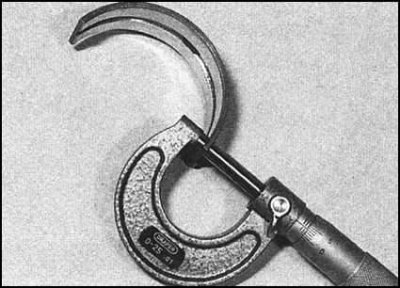
2. Alternatively (only for 1.3 l engines), the size group of the shaft journals can be determined by the thickness of the bearing shells removed from the engine. The measurement is made with a micrometer, and the size group of the necks is determined by comparing the results with those given in Specifications data. It should be noted that measuring the diameters of the necks still gives more reliable information, since by the time the need arises for an overhaul of the engine, the liners are usually far from being in the best condition.
3. Having determined the size group of the shaft journals, you can proceed to the selection of new bearing shells.
4. Main and connecting rod bearing shells are available in both standard sizes and in several repair options (with varying degrees of degradation) - cm. Specifications at the beginning of this chapter.
5. When installing the crankshaft with new liners, check the operating clearances in the bearings (see Sections Removal and installation of a head of cylinders in gathering with the inlet pipeline and a final collector and Flywheel - removal, inspection and installation).