



Contents: Engine 1.3 l ⬇ Engines 1.6 l and diesel ⬇
Engine 1.3 l
Determination of the working clearance of main bearings
1. Wipe the backs of the selected liners and their beds in the cylinder block and bearing caps.
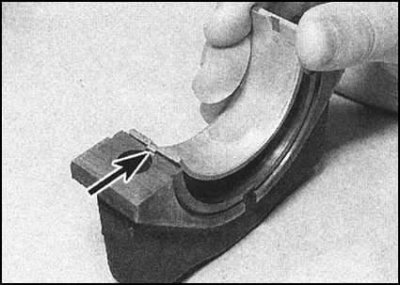
2. Insert the inserts into their beds, making sure that their tongues engage with the corresponding notches in the body of the block/covers.
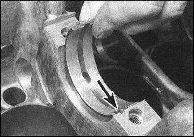
...try not to touch the working surfaces of the liners. Note that it is almost impossible to confuse the lower liners with the upper ones, due to the asymmetrical arrangement of the guide tongues. In addition, the upper liners have a groove.
3. Old liners that are suitable for use must be installed in the block and bearing caps strictly in the original order.
4. When installing a machined shaft complete with a set of branded liners from the Skoda repair kit, the need for the checks described below disappears.
5. Checking the working clearances of the main bearings should be done if there is the slightest doubt about the degree of shaft wear, as well as in the case of installing a machined shaft complete with non-brand repair liners. Determining the clearance can be done by any of the two methods described.
6. The first method, more complicated due to the need to use bore gauges and a columbus, requires the installation of main bearing caps (with inserts inserted into them) on the block. Tighten the cover mounting bolts to the required torque (old bolts are used when checking bearing clearances). Now measure the inside diameter of each bearing using a bore gauge/Columbus. Next, subtract the diameters of the corresponding crankshaft journals from the results obtained. Compare the results of the calculations with the requirements of the Specifications.
7. The second method involves using a special measuring kit Plastigage. The gap size is determined by the degree of flattening of the soft calibrated wire sections from the kit when they are compressed between the main bearing shells and the shaft journals. The width of the flattened wire sections is measured using the scale printed on the kit packaging.
8. Information about suppliers of measuring kits can be obtained at any service station.
9. Place the upper main bearing shells into their beds in the cylinder block, then carefully place the crankshaft into the block. Do not use any lubricant - the journals must be absolutely clean and dry.
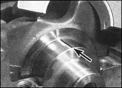
10. Cut the appropriate number of pieces of calibrated wire. The length of each piece should be slightly shorter than the length of the crankshaft journals. Place them along the journals, parallel to the axis of the latter.
11. Wipe the working surfaces of the lower liners in the bearing caps and lubricate them with a thin layer of silicone compound to prevent the calibrated wire from sticking. Install the caps in their regular places in the engine - check the factory markings. Screw in the old mounting bolts and tighten them to the required force. Do not allow the crankshaft to turn after laying the calibrated wire on it.
12. Loosen the mounting bolts evenly in several stages, then unscrew them and remove the covers, being careful not to damage the integrity of the flattened wire pieces.
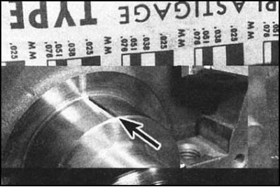
13. Using the scale on the Plastigage kit packaging, determine the working clearance of the bearings based on the degree of flattening of the calibrated wire - remember that there may be two scales on the packaging (inch and metric). Compare the measurement results with the Specification requirements.
14. If the clearance is outside the permissible limits, check whether dirt or foreign particles have gotten under the back of the liner. Wipe the backs of the liners and their beds and repeat the check. If the negative result is repeated, check the correct selection of liners (see section Replacing the intermediate shaft seal). If the calibrated wire is flattened more at one end than at the other, then the neck is tapered and must be turned.
15. If the clearance size is excessive despite the correct selection of liners, the shaft journals should be machined to install liners of the next repair size (see section Replacing the intermediate shaft seal).
16. Finally, having ensured that the bearing clearance values comply with the regulatory requirements, remove traces of flattened wire from the shaft journals by carefully scraping them off with the edge of an old credit card.
Final installation of the crankshaft
1. Carefully remove the crankshaft from the cylinder block.
2. In accordance with the instructions set out above, place the main bearing shells in their beds in the cylinder block and covers. When installing new shells, make sure that the preservative grease is completely removed from their surface - wash the shells with kerosene, then wipe thoroughly with a clean, lint-free rag. Also wipe the main journals of the crankshaft. Generously lubricate the upper shells of the main bearings of the crankshaft in the block with clean motor oil of the required grade.
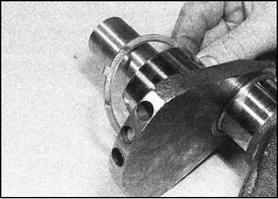
3. Place the inner thrust washer on the right crankshaft journal. Make sure that the washers are installed with the oil flow grooves facing the crank cheek.

4. After checking that it is seated correctly, carefully place the crankshaft into the cylinder block, then lubricate the lower bearings and shaft journals with clean engine oil.
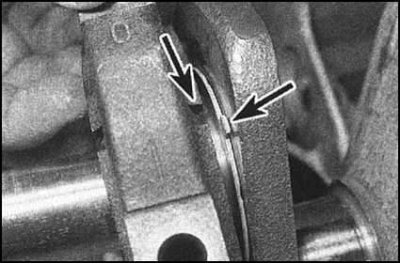
5. Turn the thrust washer with the tongue facing up so that when installing the first main bearing cap, it fits into the counter recess provided in it.
6. In accordance with the marking, install the main bearing caps in their places. Ensure that the tongue of the thrust washer is aligned with the counter recess in the first bearing cap, then firmly seat the washer in the receiving recess.
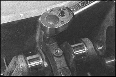
7. Screw in the cover mounting bolts and tighten them evenly in several stages to the required force.
8. Check the freedom of rotation of the crankshaft and measure the value of its axial play (see section Removal and checking the condition of the crankshaft). Before tightening the crankshaft pulley bolt, make sure that the tongues of the inner and outer thrust washers fit neatly into the corresponding grooves in the bearing cap. Inaccurate placement of the washers may result in their destruction as a result of the shaft jamming when tightening the pulley bolt.
9. Remove all traces of old gasket material and sealant from the mating surfaces of the rear oil seal housing and cylinder block.
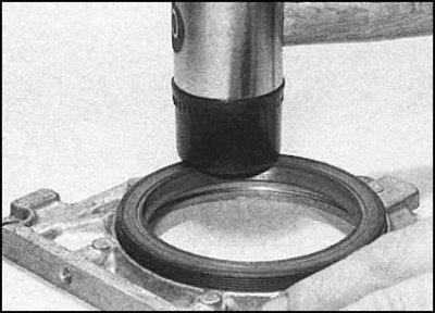
10. Carefully pry the old seal out of the casing and replace it with a new one, placing it perpendicularly on the casing's thrust shoulders (with lips inward). If necessary, use a soft-faced hammer to seat the seal.
11. If the housing was equipped with a sealing gasket during disassembly, install a new gasket on the block, carefully seating it on the guide pins. If a gasket was not provided, apply a thin layer of gasket sealant to the mating surface of the housing.
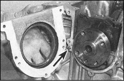
12. Carefully placing the seal on the shaft journal, press the casing onto the block, making sure that it is correctly seated on the guide pins.
13. Insert the mounting screws and tighten them securely. If using a spacer, carefully trim off the protruding edge with a sharp knife.
14. Now you can start installing the connecting rod and piston assemblies (see section Flywheel - removal, inspection and installation).
Engines 1.6 l and diesel
1. Place the cylinder block on a clean horizontal work surface with the crankcase facing up. Unbolt the bearing caps, carefully remove them from the block and lay them out in the order they were installed on the engine. If you have not done so already, remove the bearing shells from their beds in the caps and block and wipe them thoroughly with a clean, lint-free cloth.
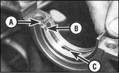
A - Sample in the bearing case; B - Insert tongue; C - Oil hole
2. Wipe the backs of the liners and their beds in the cylinder block and bearing caps. Insert the liners into the beds, making sure that their tongues engage with the corresponding grooves in the block/cap body, and that the oil holes are correctly aligned. Do not under any circumstances try to tap the liners into the bed with a hammer - their working surfaces must remain intact.
3. Once again, carefully wipe the working surfaces of the bearings and the shaft journal with a rag. Make sure that the oil flows in the crankshaft body are clear.
4. Carefully insert the crankshaft into the crankcase - try not to allow the liners to shift.
Determination of the working clearance of main bearings
1. Refer to the materials in the subsection Determining the working clearance of main bearings with the amendment that the cap fasteners should be tightened only with the force of the 1st stage.
Final installation of the crankshaft
2. Carefully remove the crankshaft from the block. Wipe the bearing surfaces. Install the thrust washers (half rings) on both sides of bed No.3, located between the second and third cylinders. To temporarily fix the half rings, use consistent grease and ensure that they are seated correctly in the receiving grooves.
Note: The thrust half rings are installed with the oil flow grooves facing outward.
3. Lubricate the upper bearing shells with clean engine oil.
4. Insert the crankshaft into the block so that the crankpins of the second and third cylinders are at TDC, and the first and fourth are at BDC.
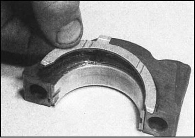
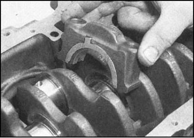
5. Lubricate the lower liners in the bearing caps, install the thrust half rings in the recesses of the 3rd bearing cap. The protruding tongues of the half rings should fit into the corresponding recesses on the walls of the cap.
Information copied from the resource: www.SkodaBook.ru
6. Install the main bearing caps onto the engine in the correct order (the first is the bearing closest to the timing belt). Make sure that the grooves for the guide tabs of the liners in the covers and the bed of the block are aligned. Screw in the cover fastening bolts (on diesel engine - new) and tighten them from installation.
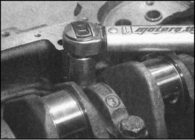
7. Working from the center outward, tighten the bolts to the first stage torque.
8. Proceeding in the same order, tighten the bolts to the 2nd stage tightening angle (use a protractor or a specially made template made of thick cardboard).
9. Install the rear oil seal housing assembly with the new oil seal inserted into it.
10. Check the freedom of crankshaft rotation. If jerks and jamming points are detected, investigate and eliminate the cause without delay - check the working clearances in the bearings again.
11. Check the shaft axial play (see section Removal and installation the cylinder head cover). If the thrust surfaces of the shaft are not worn and the half rings are replaced, the clearance should be normal.