
Marking on the piston crown
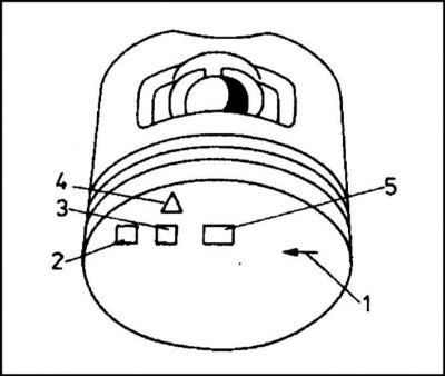
1 - Arrow indicating the direction of rotation of the crankshaft; 2 - Registration number of the manufacturer; 3 - Release date; 4 - Trademark of the manufacturer; 5 - Piston diameter (denoted by the letters A, B or C)
Piston rings
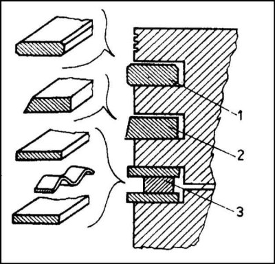
1 - First (top) compression ring; 2 - Second (bottom) compression ring; 3 - Oil scraper ring
Connecting rod and piston group - general information
Engine 1.3 l
Pistons
The pistons are made of aluminum alloy, which is characterized by high temperature resistance, significant durability and hardness.
The piston consists of a skirt and a bottom. The shape of the skirt ensures proper fit of the piston to the walls of the sleeve / cylinder, eliminating the possibility of jamming it during operation.
Inside the piston, a piston pin is installed in the bosses, with which the assembly is attached to the upper head of the connecting rod.
The axis of the hole for the piston pin is offset relative to the piston axis. This asymmetry is intended to minimize the loads that occur during the passage of the assembly TDC.
The pistons used in the considered engines have a bimetallic design: in the area of the holes for the piston pin, there are four steel belts that limit the fluctuations in the piston diameter associated with temperature changes. Thanks to this protection, it became possible to reduce the gaps between the walls of the pistons and the cylinder mirror to a value of 0.02 mm.
Three grooves are provided on the surface of the piston for the installation of piston rings. Above the groove of the first (The top compression ring has three additional grooves to limit heat transfer from the hot piston bottom to the top ring, which is in the most severe operating conditions.
Marked on the bottom of the piston.
The pistons must be matched to the sleeves/cylinders, corresponding to them in size groups. When installing connecting rod-piston assemblies in the engine, make sure that the mark in the form of an arrow is turned in the direction of rotation of the crankshaft (those. to the left of the engine).
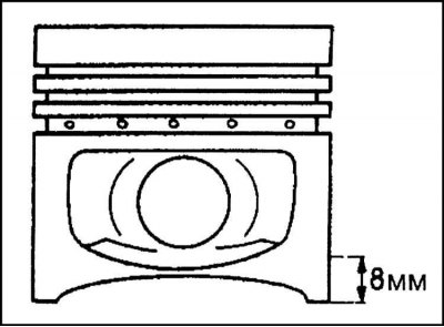
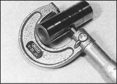
The surface of the piston skirt has a complex shape, as a result of which the diameter measurement must be carried out strictly in the specified place, at a height of 8 mm from the bottom cut of the skirt. The measurement should be made in a plane perpendicular to the axis of the piston pin. In this case, the temperature of both the piston itself and the measuring tool must be 20°C.
Pistons are available only in nominal sizes and are divided by diameter into three size groups (A, B and C).
In order to ensure stable operation of the engine, all four pistons must have the same mass. To comply with this condition, the pistons are weighed during the manufacturing process. Mass dispersion is corrected by removing metal from the skirt.
Piston pins
The piston pin provides a hinged connection between the piston and the connecting rod. The finger is made of high quality steel, ground and polished. The upper head of the connecting rod sits on the middle part of the finger. The ends of the pin are threaded into the holes in the piston bosses. Retaining rings are used to fix the finger tucked into the assembly.
The new pin is installed in the piston with little interference, no clearance or minimal clearance. In the bushing of the upper head of the connecting rod, the finger is seated with a gap. With excessive backlash, the fingers begin to knock with increasing load on the engine.
Before installing the pin, a retaining ring is installed on one side of the piston (use a special device to fit the ring). Then, from the opposite side, a piston pin lightly lubricated with engine oil is filled into the piston. The finger is filled so that its end protrudes inside the piston by 1÷1.5 mm. Next, the upper head of the connecting rod is filled into the piston, also lightly lubricated with engine oil (make sure that the oil flow hole in the upper part of the connecting rod is directed in the direction opposite to that indicated by the arrow printed on the piston crown). Next, fill the finger until it stops with its end into the retaining ring filled into the piston and install the second retaining ring on the other side of the finger.
Piston rings
Each of the pistons is equipped with three piston rings installed in grooves specially made in the upper part of the piston walls. The shape and order of fitting rings in the grooves are shown in the illustration.
The upper compression ring is made of steel and chrome-plated on the outside to reduce the friction component, as well as protect the metal from the aggressive effects of hot exhaust gases. The ring has a regular round shape and a symmetrical section in the form of a rectangle with truncated corners.
Second (bottom) the compression ring is made of cast iron and has an asymmetrical cross-section in the form of a rectangle with an inclined outer side. The angle of inclination of the outer face of the ring is about 1°, due to which the pressing of the ring against the cylinder mirror falls on a very small area. The wear of the contact pad ensures the tightness of the ring.
On one of the end surfaces of this ring there is a label in the form of an inscription "TOR". The ring should be installed on the piston with this label up.
The oil scraper ring consists of three separate sections: two narrow side rings and a wavy expander placed between them. The total thickness of the assembly is 3mm.
The oil removed by the ring from the cylinder mirror is discharged through the holes in the groove into the piston and, further, into the engine oil pan.
All piston rings are split design. The cuts of the rings are called locks, they provide the possibility of installing the rings on the pistons, and, in addition, they serve to compensate for thermal expansion.
The new ring is most tightly pressed against the cylinder mirror in the lock area. During further running-in, the clamping force gradually equalizes around the perimeter of the ring, providing maximum sealing of the assembly.
Replacing piston rings on a worn engine whose cylinders have lost their original shape leads only to a short-term restoration of compression, since the ring cannot take the shape of a worn cylinder and its tightness is unevenly distributed.
Connecting rods
The connecting rods are forged from special steel. The connecting rod consists of an upper head, a connecting rod and a lower, split head. A bronze bushing is pressed into the upper head of the connecting rod, which acts as a bearing for the piston pin. The connecting rod has an I-section. The lower head is cut in a plane perpendicular to the longitudinal axis of the assembly.

The surface of the beds for the installation of connecting rod bearing shells in the split lower head of the connecting rod is carefully processed. As a result of such processing, the interchangeability of the connecting rod bearing caps is lost, which is why special alignment marks are provided on the caps and lower heads. When factory assembled, the marks usually correspond to the numbering of the cylinders.
The cover is attached to the connecting rod by means of special high-strength bolts and two nuts with M9x1 thread.
A through hole is provided in the upper head of the connecting rod through which oil is supplied to the cylinder walls during engine operation. When installing the connecting rod, make sure that this hole is directed away from the camshaft.
By mass, the connecting rods are divided into two groups. Lighter (with a mass of 590÷598 g) marked with a yellow label applied to the head. On heavier cranks (600÷609 g) the label is blue. All connecting rods in the engine must have the same mass, and when adjusting, the mass of heavier connecting rods is reduced to the mass of lighter ones, and not vice versa.

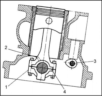
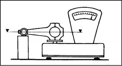
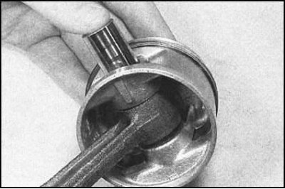
The scheme of the procedure for measuring the connecting rod car service workshop is shown in the illustration. During weighing, the connecting rod must be horizontal. The difference in the masses of the connecting rods, weighed both from the side of the lower head and from the side of the upper head, should be no more than 2 ÷ 6 g. The mass is adjusted by removing the material from the upper head and the cover of the lower head in the places indicated by arrows in the illustration. The maximum allowable thickness of the layer removed from the upper head is limited by the distance from the plane remaining after processing to the axis of the hole for installing the piston pin. For reasons of strength, this distance should be at least 15 mm. In the case of the lower head, the distance is measured from the machined plane to the axis of the connecting rod bearing and must be at least 35 mm.
Diesel engine and petrol engine 1.6L
In general, the design of connecting rod and piston assemblies is similar to that described for 1.3 liter engines, with the difference that it is possible to install oversized connecting rods (see specs). In addition, in diesel engines, the connecting rods are equipped with piston cooling oil sprayers.
Removing
Engine 1.3 l
1. Remove the cylinder head, engine sump and oil pump gears. Make sure that the cylinder liners fit securely, if necessary, fix them with special washers.
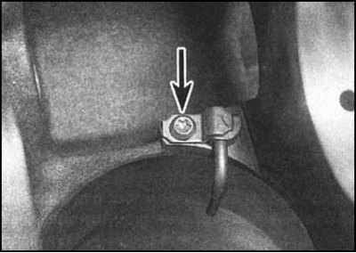
2. Check the lower connecting rod heads and connecting rod bearing caps for identification marks in the form of numbers stamped on the side of the components. The marking must correspond to the numbering of the cylinders (the cylinder closest to the gas distribution chain is considered the first).
3. If necessary, independently mark the flats machined on the connecting rods and their covers (use paint or punch).
4. Check the axial play of the connecting rods by measuring the gap between their lower heads and the crank cheeks with a blade-type feeler gauge. If the measurement result exceeds the specified Specifications value, the corresponding connecting rod must be replaced.
5. After turning the crankshaft, bring the pistons of the 2nd and 3rd cylinders to the BDC positions.
6. Give fixing nuts and remove a cover of the bottom head of a rod with the loose leaf of a rod bearing of a cranked shaft enclosed in it.
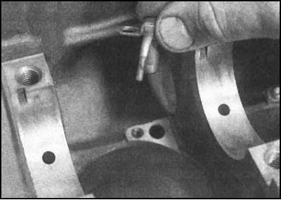
7. If dismantling is carried out only for the purpose of replacing the liners, remove the connecting rod from the shaft neck (try not to damage the neck of the shaft and the mirror of the cylinder - it is better to pull the fuel hose segments onto the bearing cap fastening studs) and remove the upper bearing shell from its head.
8. Fold the components removed from each of rods separately.
9. Remove the components of the lower heads of the connecting rods of the pistons of the 1st and 4th cylinders. Be very careful not to damage the cylinder mirrors.
10. Remove the carbonization step from the top of each cylinder.
Engines 1.6 l and diesel
1. Remove the cylinder head, oil pan, oil deflector, oil pump and oil pickup.
2. Having lowered the pistons to the middle position, feel the cylinder mirrors with your finger, checking them for stepped wear in the region of the upper limit of the piston stroke. The steps must be removed using a special countersink, as otherwise it will not be possible to exclude the possibility of damage to the pistons during the removal of the connecting rod assemblies.
3. With a scriber, scratch the number of the corresponding cylinder on the bottom of each of the pistons.
4. Using a blade-type feeler gauge, measure the end play of the connecting rods on the crankshaft journals. Write down the measurement results.
5. On the diesel engine, unscrew the fixing screws and remove the piston cooling oil nozzles from their sockets.
6. After turning the crankshaft, set the pistons of the 1st and 4th cylinders to the BDC positions. If necessary, mark the cylinder numbers on the connecting rods and covers, mark the orientation of the covers relative to the connecting rods with an arrow.
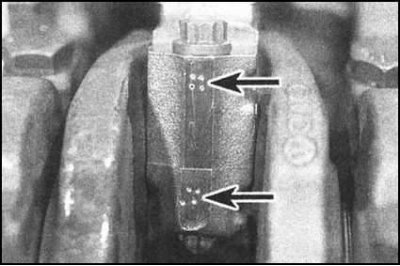
7. Try to remember the orientation of the connecting rod and piston assemblies on the engine. Depending on the type of engine, assemblies can be marked in various ways: dot marks, risks are applied on the side of the lower heads and their covers facing the timing belt, or protrusions of various shapes are provided on the casting. If the factory marking cannot be found, apply the marks yourself.
8. In several steps (half a turn per approach) loosen the cover fixing bolts, remove the cover with the lower insert. Tape the liner to the lid to avoid confusion during assembly. Repeat the procedure for assembly.
9. Using a hammer handle, push the assemblies through the cylinders, remove the upper liners and glue them with tape to the connecting rods.
10. Acting in the same order, remove the connecting rod and piston assemblies of the 2nd and 3rd cylinders.
Examination
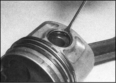
1. Insert the flat tip of a small screwdriver into the slot provided to remove the retaining ring. Heat the piston to 60°C.
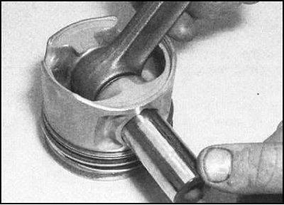
2. The pin should now be free to exit the piston and hole in the top end of the connecting rod.
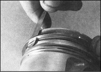
3. Arm yourself with a special tool (or with the blade of an old measuring probe) and remove the piston rings from the piston. Do not forget that the rings are made of fragile material and can easily break if the locks are opened too much - take care to protect your hands and eyes. Removed rings can be thrown away - during assembly they must be replaced without fail.
4. With a piece of the old ring, carefully remove carbon deposits from the grooves for installing the piston rings. Be careful not to damage the walls and bottom of the grooves.
5. Thoroughly clean the bottom of the pistons from carbon deposits. After scraping off the main layer of deposits, clean the bottom with a wire brush or sandpaper.
Note. Keep the piston markings intact.
6. When finished cleaning, flush the ring grooves with solvent, then dry the pistons thoroughly. Make sure that the drain oil return holes of the grooves are passable.
7. Check up a condition of pistons. Normal wear manifests itself in the form of a uniform vertical wear on the piston thrust surface and is accompanied by a loose fit in its groove of the upper compression ring. If any abnormal wear is found, the piston should be carefully examined for its suitability for further use, then an attempt should be made to identify and eliminate the cause of the violation.
8. The presence of scratches or scuffs on the piston skirt can be regarded as a result of overheating caused by a malfunction of the cooling or lubrication systems, or an unacceptable excess of the combustion temperature of the air-fuel mixture. Skirt burnouts are usually caused by blow-by gases from the combustion chambers as a result of worn cylinders or piston rings. The burnout of the piston bottom indicates the presence of violations of the ignition timing and detonation of the mixture. Piston corrosion in the form of small cavities indicates that coolant has entered the combustion chamber / engine crankcase. Try to identify the causes of violations and eliminate them.
9. Check up rods, fingers and covers of lower heads of rods on presence of cracks and other mechanical damages. After laying the connecting rods on a flat surface, check them for signs of deformation (if you are unsure, contact a car service specialist for help). Estimate a condition of plugs of the top heads of rods.
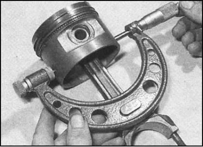
10. Using a micrometer, measure the diameters of all four pistons at a distance of 10 mm from the cut of its skirt in a plane located at right angles to the axis of the piston pin. If the measurement result is outside the specified Specifications range, the piston must be replaced.
Note. If during the overhaul the cylinder block was bored or the liners were replaced (models 1.3 l), you should choose a new set of oversized pistons. Write down the measurement results - they will be required later when calculating the clearances of the pistons in the cylinders (see below).
11. Inserting a new piston ring into the corresponding groove on the piston, use a blade-type feeler gauge to measure the ring seat clearance. Check the fit of each piston ring one by one. If the result of any of the measurements is out of range, the piston must be replaced. Just in case, check the correct choice of rings by measuring their thickness with a micrometer.
12. Using a vernier Columbus, measure the inner diameters of the piston pin seats in the upper ends of the connecting rods. Then determine the diameters of the fingers). Subtracting the results of the last measurements from the results of the first measurements, determine the clearances of the fingers in the heads. Compare calculation results with requirements Specifications. If necessary, the connecting rod bushing and the seat in the piston must be machined, and the pin replaced with a new, repair size. It would be better to entrust this work to car service specialists.
13. On 1.3 liter engines, the connecting rods are divided into two weight categories, the corresponding markings are applied to the covers of the lower heads of the connecting rods. Lighter connecting rods are marked with yellow paint, heavier ones with blue. When replacing connecting rods, replaceable components from the same weight group should be selected. If there is no marking, you should seek advice from the specialists of the Skoda branded service center.
14. The correct orientation of the pistons on the connecting rods is determined by the markings applied to the bottoms (the bottom must be cleaned of soot).
15. On 1.3 liter engines, the arrow printed on the piston crown should point forward along the engine (towards the oil filter). The connecting rod must be turned back by the oil currents.
16. On 1.6L models and diesel engines, the arrow on the piston crown must point towards the timing belt. The connecting rod and the cover of its lower head are installed by a groove made in their bases in the direction indicated by the arrow on the piston.
17. Grease a piston pin and the plug of an upper head of a rod with pure motive oil. Install the piston on the connecting rod. Secure the finger with two retaining rings, turning them 180°from the removable grooves with the locks. Proceeding in the same order, mount the remaining connecting rod and piston assemblies.